Pumping system and engineering machinery

A pumping system and construction machinery technology, applied in the field of construction machinery and pumping systems, can solve problems such as unsuccinct and beautiful appearance of the hopper, poor heat dissipation performance of the vibration motor, and potential safety hazards for operators, so as to reduce procurement costs, Beautiful appearance and improved service life

Active Publication Date: 2013-01-02
SANY AUTOMOBILE MFG CO LTD
View PDF6 Cites 4 Cited by
  • Summary
  • Abstract
  • Description
  • Claims
  • Application Information

AI Technical Summary

Problems solved by technology

[0004] The vibrating motor is used to drive the screen to vibrate. Usually, when the pump truck is working, the concrete will erode the vibrating motor. If it is not cleaned in time, a hard-to-remove concrete layer will be formed on the vibrating motor, resulting in poor heat dissipation performance of the vibrating motor. It is good but the motor burns out, this kind of failure often occurs in actual use
Moreover, the vibration motor is a purchased part and is not easy to maintain
[0005] The mechanical mechanism is used to transfer the power source of the stirring motor to the screen. Although the problem of burning out of the vibration motor and difficult maintenance is reduced, the mechanical mechanism is located on the side of the hopper. When the pump truck is working, the movement of the mechanical mechanism will give the operator It brings great safety hazards, and the structure of the mechanism is relatively complicated, and the overall appearance structure of the hopper is not simple and beautiful

Method used


Image

  • Pumping system and engineering machinery
  • Pumping system and engineering machinery
  • Pumping system and engineering machinery

Examples


Embodiment Construction

[0040] In order to enable those skilled in the art to better understand the technical solutions of the present invention, the present invention will be further described below in conjunction with the accompanying drawings and embodiments. It should be noted that, in the case of no conflict, the embodiments of the present application and the features in the embodiments can be combined with each other.

[0041] In the following description, many specific details are set forth in order to fully understand the present invention. However, the present invention can also be implemented in other ways than described here. Therefore, the protection scope of the present invention is not limited by the specific implementation disclosed below. Example limitations.

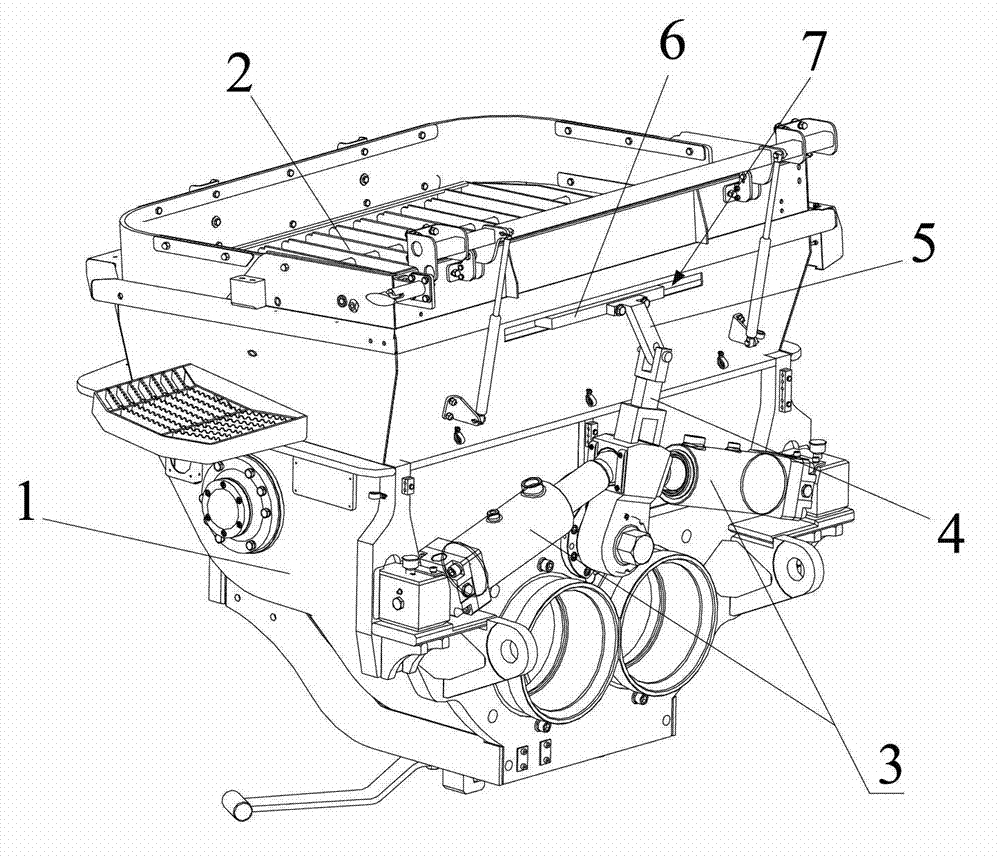
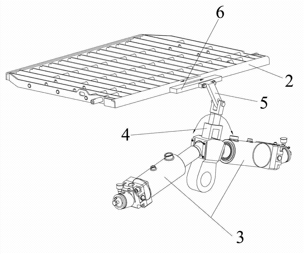
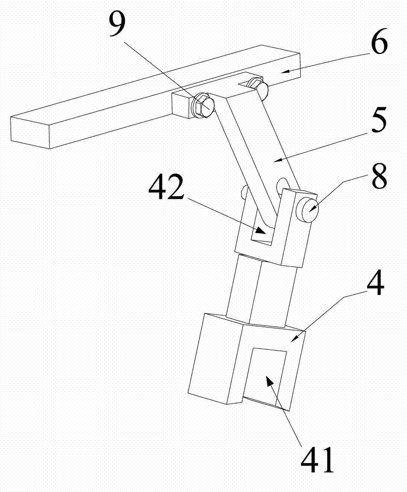
[0042] like Figure 1 to Figure 6 As shown, the present invention provides a pumping system, including a hopper, a distribution valve and a swing cylinder 3, the hopper includes a bucket body 1 and a screen 2, the pumping syst...


PUM


Abstract

The invention provides a pumping system; the pumping system comprises a hopper, a distribution valve and a swinging oil cylinder, wherein the hopper comprises a hopper body and a screen; the pumping system further comprises an earing; the screen is mounted at a material inlet of the hopper body; the screen is connected with a hopper body moving pair; the distribution valve is mounted in the hopper body; one end of the swinging oil cylinder is hinged on the hopper body and the other end of the swinging oil cylinder is used for driving the distribution valve to rotate; one end of the earing is connected with the other end of the swinging oil cylinder; the other end of the earing is connected with the screen in a rotating way; and while driving the distribution valve to rotate, the swinging oil cylinder can be used for driving the screen to move through the earing. The invention further provides engineering machinery. According to a technical scheme provided by the invention, the screen can be directly supplied with power by the swinging oil cylinder instead of a motor to vibrate; and as a vibrating device for swinging the screen is positioned behind the hopper and a swinging protective cover is arranged outside the hopper for protection, the whole hopper is simpler, beautiful and elegant.

Description

technical field [0001] The invention relates to the field of material pumping, and more specifically, to a pumping system and construction machinery including the pumping system. Background technique [0002] At present, on the concrete pump truck hopper, the vibration of the screen is usually provided by the vibration motor. Some manufacturers put the vibration motor on the screen; some manufacturers hang the vibration motor on the side of the hopper. [0003] Screen vibration is also driven by an external power source, which uses a mechanical mechanism to transmit the power source of the stirring motor to the screen to achieve the effect of screen vibration. [0004] The vibrating motor is used to drive the screen to vibrate. Usually, when the pump truck is working, the concrete will erode the vibrating motor. If it is not cleaned in time, a hard-to-remove concrete layer will be formed on the vibrating motor, resulting in poor heat dissipation performance of the vibrating ...

Claims


Application Information

Patent Timeline
Patent Type & Authority Applications(China)
IPC IPC(8): E04G21/02
Inventor 谢邵辉熊岚刘杰
Owner SANY AUTOMOBILE MFG CO LTD
Why Eureka
Try Eureka