Continuously variable valve lift system

A valve lift and variable technology, which is applied to valve devices, machines/engines, mechanical equipment, etc., can solve the problems of incomplete engine performance, high cost, complex structure, etc., and achieves convenient and fast control, easy manufacturing and installation, The effect of simple structure principle

Active Publication Date: 2013-01-02
HANGZHOU BRANCH ZHEJIANG GEELY AUTOMOBILE RES INST +2
View PDF5 Cites 9 Cited by
  • Summary
  • Abstract
  • Description
  • Claims
  • Application Information

AI Technical Summary

Problems solved by technology

[0004] The purpose of the present invention is to provide a new type of continuously variable valve lift system, which solves the problems of incomplete engine performance improvement, complex structure and high cost of current valve lift systems.

Method used


Image

  • Continuously variable valve lift system
  • Continuously variable valve lift system
  • Continuously variable valve lift system

Examples


Embodiment Construction

[0034] In order to make the purpose, technical solutions and advantages of the embodiments of the present invention more clear, specific embodiments will be described in detail below with reference to the accompanying drawings.

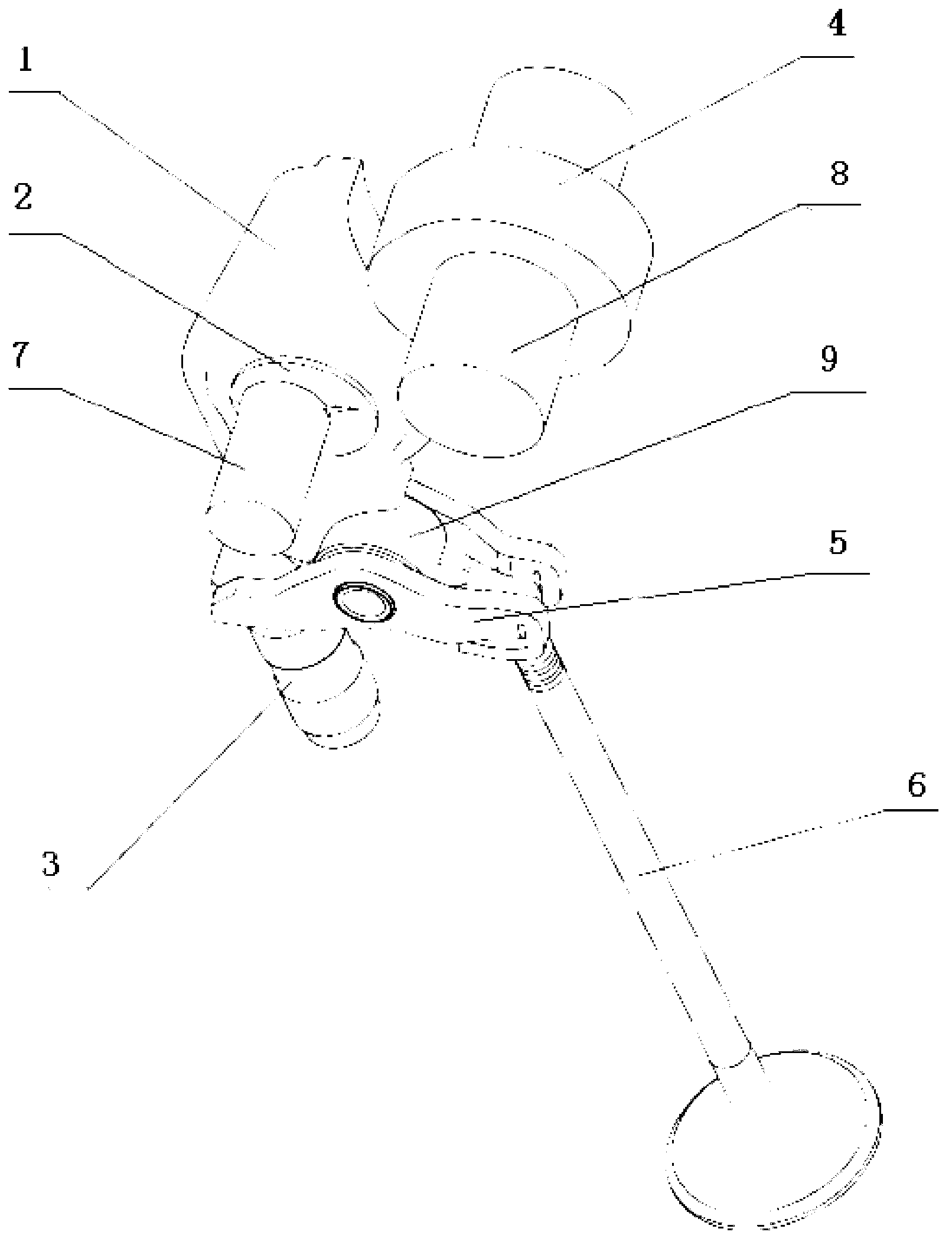
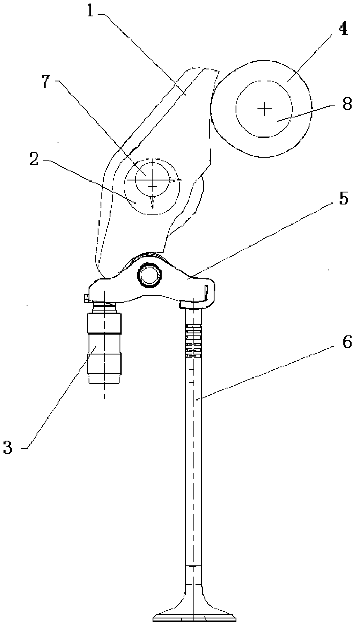
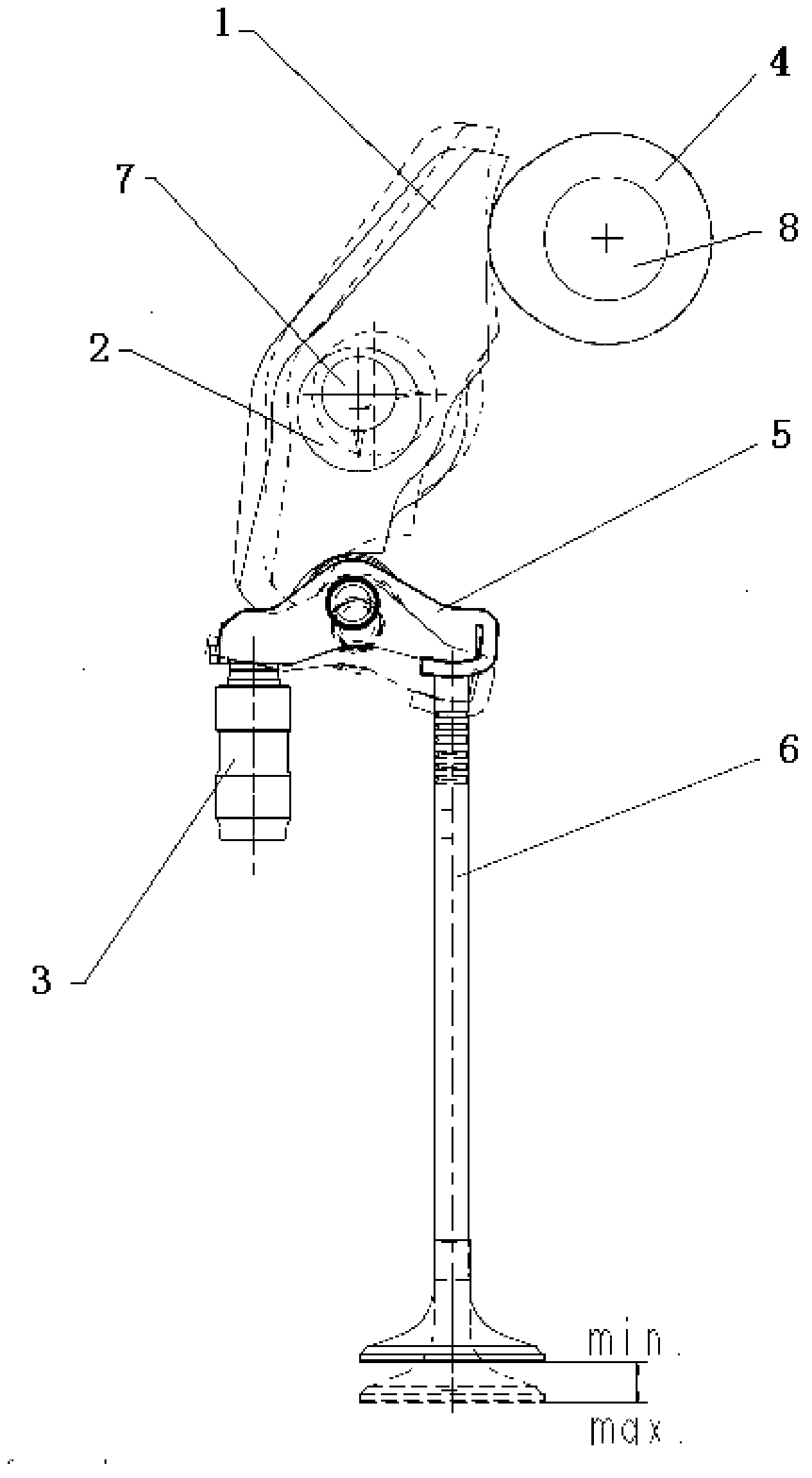
[0035] Figure 1-6 As shown, the embodiment of the present invention provides a continuously variable valve lift system, including:

[0036] The first rocker arm 5, the bottom side of its first end is in contact with the valve 6 and can push the valve 6, and the bottom side of the second end is supported by the hydraulic tappet 3, that is, the first rocker arm 5 can rotate around the hydraulic tappet 3.

[0037] The driving cam 4 is fixed on the camshaft 8 .

[0038] The second rocker arm 1, the drive cam 4 contacts and pushes the first end of the second rocker arm 1, and the second end of the second rocker arm 1 contacts and pushes the first rocker arm 5, that is, the valve The driving force of 6 is provided by the second rocker arm 1.

[0039] Th...


PUM


Abstract

The invention discloses a continuously variable valve lift system, which relates to the field of engine valve design; the continuously variable valve lift system comprises a first rocker arm; the bottom side of a first end of the first rocker arm is in contact with a valve and can push the valve; the bottom side of a second end of the first rocker arm is supported by a hydraulic tappet; the continuously variable valve lift system further comprises a second rocker arm which is used for pushing the first rocker arm and driven by a fixedly arranged driving cam; the second rocker arm is arranged on an eccentric wheel and uses the center of the eccentric wheel as rotation center; the position of the rotation center of the second rocker arm is changed; correspondingly, directions and sizes of a power arm and a resisting arm as well as an angle between the second rocker arm and a horizontal plane are changed; and then the rotation quantity of the first rocker arm is driven to be changed; and finally, the lift of the valve in contact with the first rocker arm is changed; and according to the invention, problems of incomplete performance, complicated structure and expensive manufacturing cost of a lifting engine of the traditional valve lift system are solved.

Description

technical field [0001] The invention relates to the field of engine valve design, in particular to a continuously variable valve lift system. Background technique [0002] For a traditional gasoline engine, the valve lift is fixed, and the engine load is adjusted by controlling the throttle opening. Such a control method causes the engine to have a large pumping loss, especially under partial load, the pumping loss is more serious, which will greatly affect the performance of the engine. [0003] Therefore, major international automobile groups have invested a large amount of funds and manpower in the research and development of variable valve lift technology. At present, the continuously variable valve lift technology can change the valve lift according to the operating conditions of the engine, so that the throttle valve is always within a relatively large opening range, which can effectively reduce fuel consumption and emissions, and improve engine power and torque. fea...

Claims


Application Information

Patent Timeline
Patent Type & Authority Applications(China)
IPC IPC(8): F01L13/00
Inventor 卢本友刘岩沈源由毅赵福全
Owner HANGZHOU BRANCH ZHEJIANG GEELY AUTOMOBILE RES INST
Why Eureka
Try Eureka