water flow engine

An engine, water flow technology, applied in the direction of engine components, machines/engines, reaction engines, etc., can solve problems such as disadvantage, low flow rate, poor hull stability, etc.

Active Publication Date: 2016-11-30
徐传付
View PDF4 Cites 0 Cited by
  • Summary
  • Abstract
  • Description
  • Claims
  • Application Information

AI Technical Summary

Problems solved by technology

[0004] Because although the flow rate of the ocean current is large, the flow velocity is relatively small. In order to obtain greater water flow energy, a large section of water flow perpendicular to the direction of the water flow must be intercepted. It is greatly restricted, because the hull bears a large load, and the stability of the hull becomes extremely poor. At the same time, the shaft of the water wheel and the bushing on the hull are under great radial pressure, which is extremely unfavorable to the shaft of the water wheel and the hull. The water wheels and blades of this barge-type current power station cannot be made too large, so although the barge-type current power station uses a larger barge, it cannot obtain a large flow energy of a large cross-section perpendicular to the flow direction.

Method used


Image

  • water flow engine
  • water flow engine
  • water flow engine

Examples


Embodiment Construction

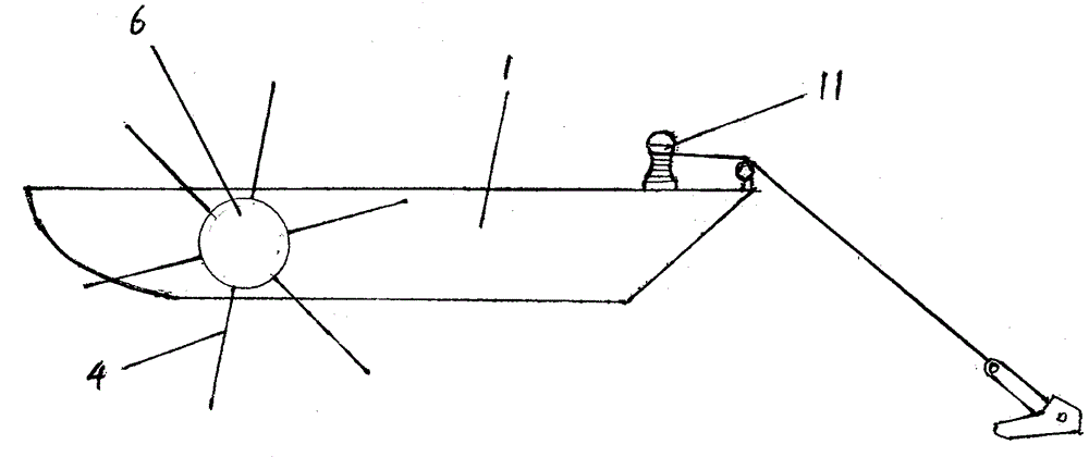
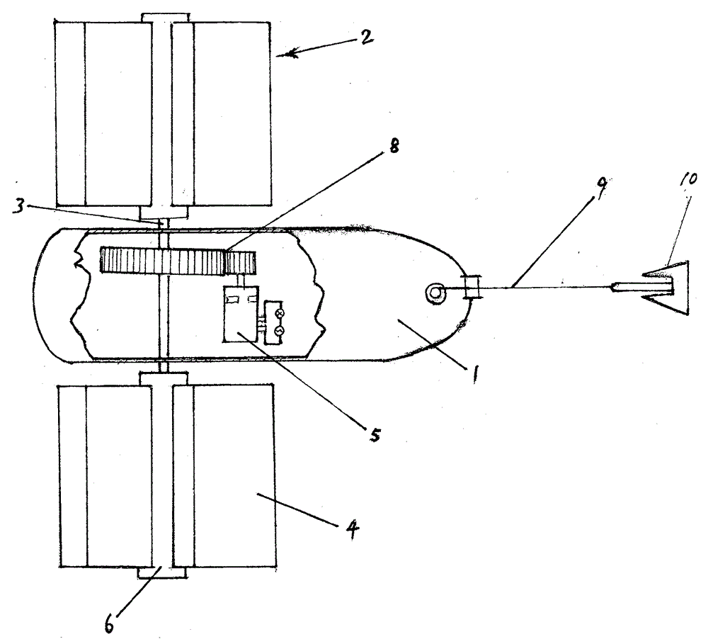
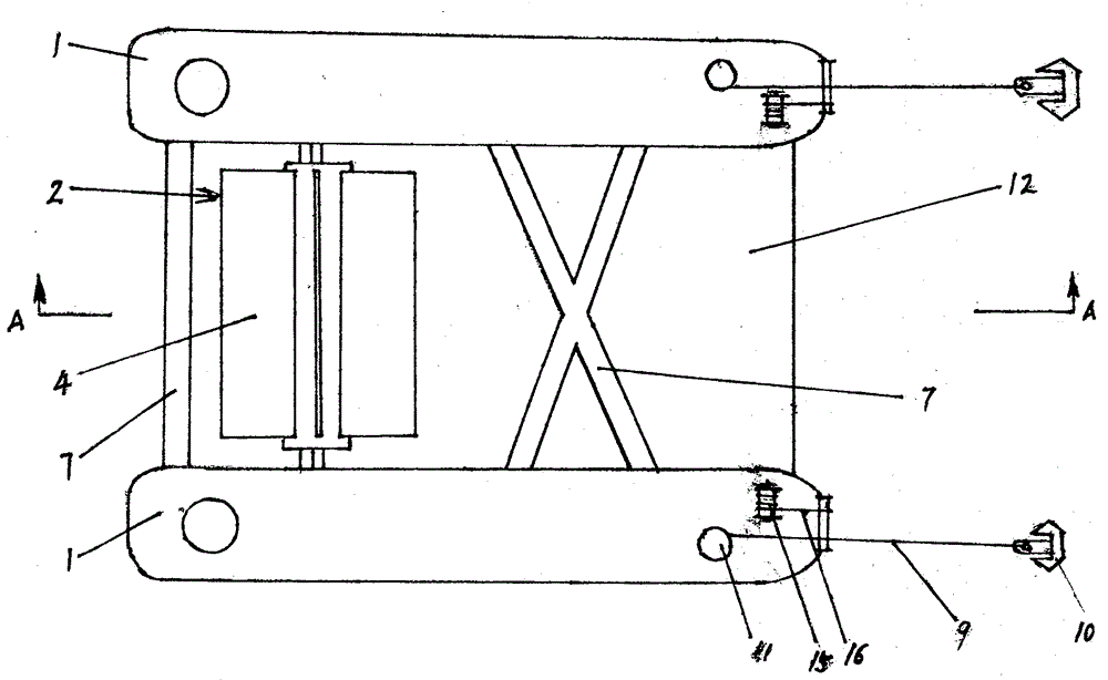
[0020] figure 1 It is a side view of the water flow engine described in the present invention, figure 2 yes figure 1 A top view of , with parts cut away. The figure shows that a water wheel 2 is respectively installed on both sides of the ship's side of the hull 1, and the water wheel shaft of the water wheel 2 passes through the shaft hole arranged on the ship's side and is connected with the speed change device 8 shafts in the hull 1, and then connected with the generator 5 Axis links to each other, is also provided with floating roller 6 around the water wheel shaft 3 that stretches in hull 1 outside, and floating roller 6 is the garden pipe that is symmetrical with water wheel shaft 3 axis, and its two ends are welded into one with annular garden plate, makes floating roller 6 constitute A sealed space. Six blades 4 symmetrical to the water wheel axis are arranged around the floating roller 6, and the buoyancy generated by the part of the water wheel 2 submerged in the...


PUM


Abstract

The invention discloses a water flow engine, aiming to provide a water flow energy conversion device which has high energy conversion efficiency, can obtain a large amount of water flow energy, and floats stably on the water surface with water flow. The device comprises a hull (1), a water wheel shaft (3) passing through the water wheel (2) on the side of the ship, and the water wheel shaft (3) can be linked with a speed change device (8) and a generator (5) shaft drive in the hull, said The water wheel (2) is provided with floating rollers (6) on the outside of the hull, and the floating rollers (6) are hollow rotating bodies coaxial with the water wheel shaft. of the leaves. The buoyancy produced by the floating roller floating on the water surface can support the dead weight of the whole water wheel (2). The device is anchored on rivers, oceans and other water surfaces with currents, and can effectively convert the kinetic energy of water flow into the mechanical energy of water wheel shaft rotation. The device can drive the generator to generate electricity, thus providing people with a huge renewable energy. Cheap clean energy.

Description

[0001] The technical field [0002] The invention relates to a device for utilizing water flow energy, in particular to a device that floats on the water surface and can convert the kinetic energy of the flowing water flow in rivers and oceans into mechanical energy that can be used by people and then into electrical energy. Background technique [0003] There are a lot of water flow in nature, which has great kinetic energy, and it is an inexhaustible renewable new energy source. A large amount of seawater in the ocean is constantly flowing with currents according to certain rules. There are also tidal currents near the mouths of rivers, and there are also currents flowing from upstream to downstream in large rivers and rivers. At present, people have not widely developed and utilized these currents. People have designed some devices that can utilize water flow, but their conversion efficiency is too low. In recent years, the United States has developed a barge type ocean cu...

Claims


Application Information

Patent Timeline
Patent Type & Authority Patents(China)
IPC IPC(8): F03B13/00F03B3/18
Inventor 徐传付
Owner 徐传付
Why Eureka
Try Eureka