
Down lamp capable of dissipating heat through convection of inner passage and outer passage

A technology of downlights and channels, which is applied in lighting and heating equipment, components of lighting devices, cooling/heating devices of lighting devices, etc., can solve problems such as poor heat dissipation, heat island effect that cannot solve local high temperature heat dissipation, and increased costs

Active Publication Date: 2013-01-02
KINGSUN OPTOELECTRONIC CO LTD
View PDF6 Cites 5 Cited by
  • Summary
  • Abstract
  • Description
  • Claims
  • Application Information

AI Technical Summary

Problems solved by technology

[0003] Existing LED downlights use a single radiator or a radiator plus a fan. The radiator plus a fan will increase the cost and require additional power supply; while the existing single radiator usually uses heat conduction and heat dissipation. Heat dissipation is carried out by increasing the contact area between the heat sink and the external air. However, this heat dissipation effect cannot solve the heat island effect of local heat dissipation and high temperature in contact with the heat source, and it is easy to cause poor heat dissipation; there are also structures that use convection heat dissipation to dissipate heat through air convection. However, the radiator of the existing convection heat dissipation structure adopts several closed heat dissipation channels, and the heat needs to be dissipated through the outer shell of the radiator.

Method used


Image

  • Down lamp capable of dissipating heat through convection of inner passage and outer passage
  • Down lamp capable of dissipating heat through convection of inner passage and outer passage
  • Down lamp capable of dissipating heat through convection of inner passage and outer passage

Examples


Embodiment Construction

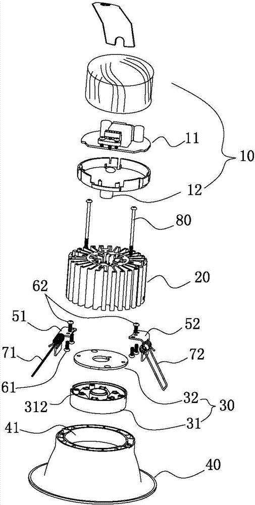
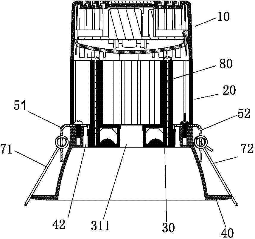
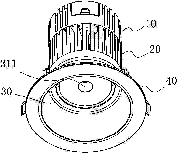
[0027] The following will be combined with Figure 1-7 An example for further details:

[0028] A downlight with convection heat dissipation through internal and external channels in the embodiment includes: an electrical module 10, a heat sink 20, an optical engine 30 and a lampshade 40, and the electrical module 10 includes an LED control circuit board 11 with an external power supply.

[0029] The radiator 20 is mainly composed of a cylinder cavity 21 and a number of heat dissipation ribs 22 connected to the outside of the cylinder cavity 21 from top to bottom at intervals. ; An open external convection heat dissipation channel 24 is formed between every two adjacent heat dissipation fins 22 .

[0030] The optical engine 30 includes a module lens 31, an aluminum substrate 32 and several LEDs 33, the center of the module lens 31 has a module lens through hole 311 for convection heat dissipation, and the center of the aluminum substrate 32 has an aluminum substrate for conve...


PUM


Abstract

The invention relates to a down lamp capable of dissipating heat through convection of an inner passage and an outer passage. The down lamp comprises an electrical appliance module, a radiator, an optical engine and a lampshade, wherein the electrical appliance module is arranged on the top end face of the radiator, and an LED (Light Emitting Diode) control circuit board in the electrical appliance module is electrically connected with the optical engine through a wire; the optical engine is fixedly connected to the bottom end face of the radiator and enables a module lens through hole and an aluminum substrate through hole in the optical engine to be communicated with an inner closed convection heat dissipation passage in the radiator; the section of the optical engine is less than the section of the radiator, so that the peripheral space of the optical engine is communicated with an open outer convection heat dissipation passage of the radiator; an upper open gap of the lampshade is sleeved outside the optical engine and then is fixedly connected with the bottom surface of the radiator; and an outer ring hole is formed between an upper opening of the lampshade and the optical engine and is communicated with the bottom of the open outer convection heat dissipation passage. After the structure is adopted, the down lamp has the characteristics of novel and skillful structure, light weight, low cost and good internal and external convection heat dissipation effect.

Description

technical field [0001] The invention relates to the technical field of LED downlights, in particular to a downlight which dissipates heat through convection through internal and external passages. Background technique [0002] With the continuous development of lighting technology, various lamps are constantly being introduced. LED downlight lighting fixtures have been widely used in many occasions due to their advantages of energy saving and environmental protection. However, how to better dissipate heat from LED downlights has become a difficult point in LED downlight lighting technology. [0003] Existing LED downlights use a single radiator or a radiator plus a fan. The radiator plus a fan will increase the cost and require additional power supply; while the existing single radiator usually uses heat conduction and heat dissipation. Heat dissipation is carried out by increasing the contact area between the heat sink and the external air. However, this heat dissipation e...

Claims


Application Information

Patent Timeline
IPC IPC(8): F21S2/00F21V29/00F21V17/12F21Y101/02F21V29/77
Inventor 李善良
Owner KINGSUN OPTOELECTRONIC CO LTD
Learn More