Illuminator

A lighting device and light source technology, applied in the field of lighting, can solve the problems of poor heat dissipation effect of the lighting device, and achieve the effects of ensuring service life, easy assembly, and simple structure

Inactive Publication Date: 2013-01-02
CIVILIGHT SHENZHEN SEMICON LIGHTING
View PDF5 Cites 5 Cited by
  • Summary
  • Abstract
  • Description
  • Claims
  • Application Information

AI Technical Summary

Problems solved by technology

[0003] The purpose of the embodiment of the present invention is to provide a lighting device, aiming to solve the problem of poor heat dissipation effect of the existing lighting device

Method used


Image

  • Illuminator
  • Illuminator
  • Illuminator

Examples


Embodiment 1

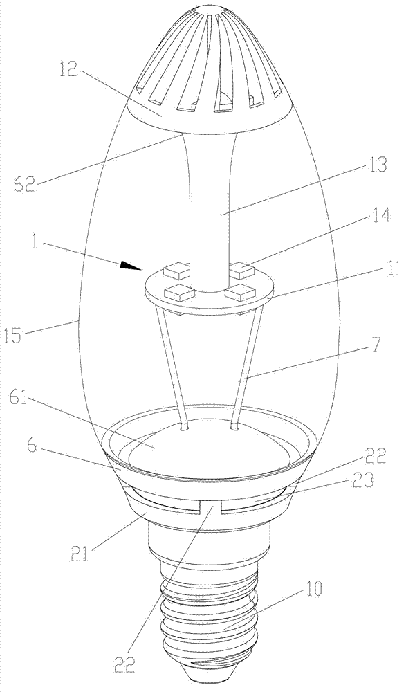
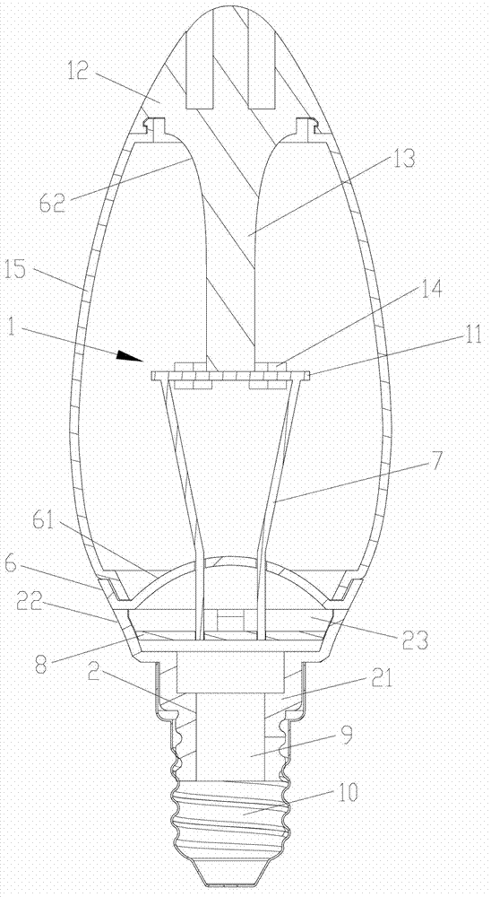
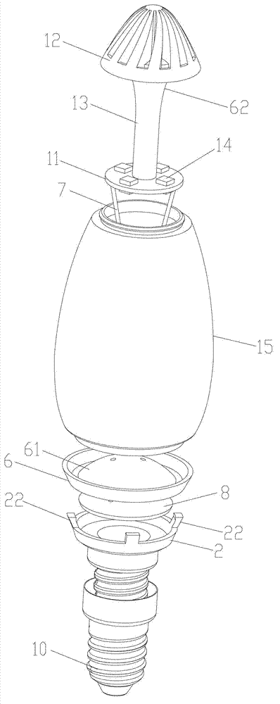
[0024] like Figure 1~3 As shown, the lighting device provided by the embodiment of the present invention includes a light source 1 and a driving power supply 2 for powering the light source 1 , and the light source 1 is mounted on a light source radiator 12 thermally isolated from a power radiator 21 . In this way, the heat dissipation of the light source 1 and the driving power supply 2 is separated, and the heat dissipation of the two is relatively independent, and no longer interacts with each other.

[0025] Usually, the top of the power radiator 21 is provided with a plurality of heat-insulating buckles 22 fixedly connected to the heat sink 6 , and gaps 23 for air flow are formed between adjacent heat-insulating buckles 22 . In this way, the air flow will quickly take away the heat transferred to the power radiator 21 and the heat sink 6, and the heat dissipation is very fast and timely.

[0026] In the embodiment of the present invention, a transparent cover 15 is prov...

Embodiment 2

[0029] The difference from Embodiment 1 is that the heat sink 6 in this embodiment is provided with a support column 63 for supporting the light source 1, and the heat generated by the light source 1 is transmitted to the heat sink 6 through the support column 63, and then released to the surrounding air , to further improve the heat dissipation efficiency of the light source 1, such as Figure 4 shown.

Embodiment 3

[0031] like Figure 5 As shown, in this embodiment, the light source radiator 12 and heat dissipation seat 6 described in Embodiments 1 and 2 are all provided with a plurality of guide holes 16 for air flow to pass through, which is beneficial to make the heat transfer to the light source radiator 12 and heat dissipation seat 6 heat is quickly released to the air, and forms convection with the outside air, quickly taking away the heat released to the air. At this time, the guide hole 16 and the gap 23 form an all-round heat flow channel up, down, left, and right, which further improves the heat dissipation effect of the lighting device. In order to prevent the light source 1 from being polluted by impurities in the outside air, the light source 1 is covered by a protective shell 3 . Wherein, the protective shell 3 is roughly located in the middle of the light-transmitting cover 15 , so that the air between the light-transmitting cover 15 and the protective shell 3 can form st...


PUM


Abstract

The invention provides an illuminator, belonging to the field of illumination technology. The illuminator comprises a light source and a driving power supply for supplying power for the light source, and the light source is mounted on a light-source radiator thermally isolated from a power radiator. According to the invention, the light source is mounted on the light-source radiator thermally isolated from the power radiator, therefore, heat radiation of the light source and the driving power supply is isolated, relatively independent from each other and no longer mutually influenced. The heat radiation effect is excellent, and service lives of the light source and the driving power supply are both guaranteed, thus being beneficial for prolonging the service life of the illuminator. Therefore, the illuminator can be applied for various light source products or lamp products requiring independent power supply devices, such as halogen lamps, electric discharge lamps, fluorescent lamps, car lamps, high voltage sodium lamp, semiconductor energy-saving lights, solid semiconductor head lamps (LED (light-emitting diode)/OLED(organic light emitting diode)), reflector lamps, modulator tubes, and the like.

Description

technical field [0001] The invention belongs to the technical field of lighting, and in particular relates to a lighting device. Background technique [0002] At present, there is only one heat sink in various lighting devices on the market, and both the light source and the driving power are dissipated through the heat sink. Although this is beneficial to assembly, the heat dissipation effect is not good. Contents of the invention [0003] The purpose of the embodiments of the present invention is to provide a lighting device, aiming to solve the problem of poor heat dissipation effect of the existing lighting device. [0004] The embodiment of the present invention is realized in the following way: an illuminating device includes a light source and a driving power supply for the light source, and the light source is installed on a light source heat sink thermally isolated from the power heat sink. [0005] In the embodiment of the present invention, the light source is...

Claims


Application Information

Patent Timeline
Patent Type & Authority Applications(China)
IPC IPC(8): F21S2/00F21V29/00F21V19/00F21V29/71
CPCY02B20/36Y02B20/30
Inventor 薛信燊全宗丰
Owner CIVILIGHT SHENZHEN SEMICON LIGHTING
Why Eureka
Try Eureka