Solder paste thickness measuring bracket
A technology for thickness measurement and solder paste, which is applied in the field of solder paste thickness measurement brackets, can solve problems such as the inability to accurately measure the thickness of solder paste, achieve the effects of simple structure, convenient use, and improved thickness measurement accuracy
- Summary
- Abstract
- Description
- Claims
- Application Information
AI Technical Summary
Problems solved by technology
Method used
Image

Examples
Embodiment 1
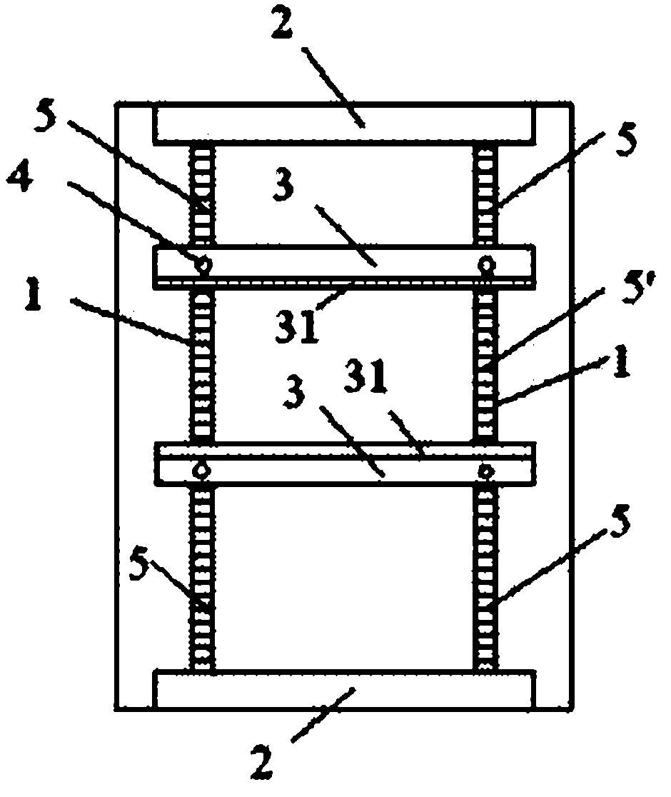
[0019] Such as figure 1 As shown, the solder paste thickness measuring bracket of the present invention includes two slide rails 1 , and a baffle plate 2 as a limiting component is respectively fixed at the ends of the slide rails 1 . Two clamping parts 3 parallel to each other are slidably arranged on the slide rail 1 , and a recess 31 is provided on opposite sides of the two clamping parts 3 for supporting the object to be measured. The above-mentioned baffle plate 2 can effectively prevent the clamping part 3 from slipping out of the slide rail 1 during the sliding process.
[0020] A bolt 4 as a locking element is also arranged on the clamping part 3 , the bolt 4 passes through the above-mentioned clamping part 3 vertically, and the bottom of the bolt 4 is located above the slide rail 1 . When the bolt 4 is tightened downwards, the bottom is tightly pressed against the slide rail 1 , thereby fixing the clamping part 3 and the slide rail 1 .
Embodiment 2
[0022] in such as figure 1 As shown, the difference between this embodiment and Embodiment 1 is that the solder paste thickness measuring bracket in this embodiment further includes four springs 5 as elastic components. The four springs 5 are all worn on the slide rail 1, and are separated between the baffle plate 2 and the clamping part 3 on the same side, and the two ends of the same spring 5 are respectively pressed against the baffle plate 2 and the clamping part 3 on. When the object to be measured is clamped between the two clamping parts 3, the springs 5 are both compressed, and the restoring force of the springs on both sides tends to bring the two clamping parts 3 closer to each other so as to clamp the object to be measured.
[0023] The elastic component and the locking piece of the solder paste thickness measuring bracket exist at the same time, which can achieve the purpose of further fixing the clamping component 3 . Of course, the locking piece or the el...
Embodiment 3
[0025] Another example figure 1 As shown, the difference between this embodiment and Embodiment 2 is that the spring 5' in this embodiment is arranged between the two clamping parts 3 to replace the spring 5 in Embodiment 2. When the object to be measured is clamped between the two clamping parts 3, the spring 5' is stretched, and the restoring force of the spring 5' tends to bring the two clamping parts 3 closer to each other so as to clamp the object to be measured. The remaining parts are exactly the same as those in Embodiment 2, and will not be repeated here.
PUM
 Abstract
Description
Claims
Application Information
 - R&D
- Intellectual Property
- Life Sciences
- Materials
- Tech Scout
- Unparalleled Data Quality
- Higher Quality Content
- 60% Fewer Hallucinations
Browse by: Latest US Patents, China's latest patents, Technical Efficacy Thesaurus, Application Domain, Technology Topic, Popular Technical Reports.
© 2025 PatSnap. All rights reserved.Legal|Privacy policy|Modern Slavery Act Transparency Statement|Sitemap|About US| Contact US: help@patsnap.com