
Integral detection method of intelligent substation electric energy metering device

A technology of electric energy metering device and intelligent substation, which is applied in the direction of measuring device, measuring electrical variable, instrument, etc., to achieve the effect of strong operability and simple method

Inactive Publication Date: 2013-01-02
ELECTRIC POWER RES INST STATE GRID JIANGXI ELECTRIC POWER CO +1
View PDF3 Cites 8 Cited by
  • Summary
  • Abstract
  • Description
  • Claims
  • Application Information

AI Technical Summary

Problems solved by technology

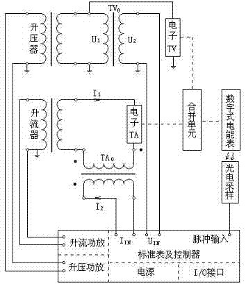
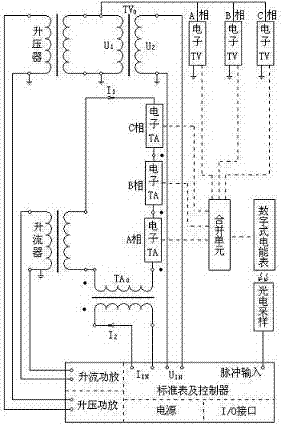
[0005] The purpose of the present invention is to solve the current domestic lack of digital electric energy metering device inspection technical means, and various electronic transformer manufacturers' compliance with the IEC61850-9-1 / 2 statute Inconsistent understandings, inconsistent "languages" of manufactured electronic transformers, digital electric energy meters do not have an interface for on-site verification and cannot be verified on-site, etc. The present invention provides a smart substation electric energy metering device Detection method

Method used


Image

  • Integral detection method of intelligent substation electric energy metering device
  • Integral detection method of intelligent substation electric energy metering device

Examples


Embodiment 1

[0039] (3) Control the boost power amplifier to raise the voltage to the rated voltage;

[0040] (4) Control cosφ=1.0 and step-up power amplifier to increase the current to 1%I b , at this time, the electric energy pulse output LED light-emitting tube on the digital electric energy meter should have light pulse output with alternating light and dark;

[0041] (5) Properly adjust the photoelectric sampler to align with the electric energy pulse output LED light-emitting tube, so that the LED light-emitting tube on the photoelectric sampler is consistent with the flickering frequency of the digital electric energy pulse output LED light-emitting tube;

[0042] (6) Start the overall error detection of single-phase sub-components. From the standard electric energy meter and the controller, it can be read that the measurement device of this phase is at cosφ=1.0, 1%I b The overall error value in the state;

[0043] (7) Raise the current to 5%I under the same conditions as above b...

Embodiment 2

[0048] (3) Control the boost power amplifier to raise the voltage to the rated voltage;

[0049] (4) Control cosφ=1.0 and step-up power amplifier to increase the current to 1%I b , at this time, the electric energy pulse output LED light-emitting tube on the digital electric energy meter should have light pulse output with alternating light and dark;

[0050] (5) Properly adjust the photoelectric sampler to align with the electric energy pulse output LED light-emitting tube, so that the LED light-emitting tube on the photoelectric sampler is consistent with the flickering frequency of the digital electric energy pulse output LED light-emitting tube;

[0051] (6) Start the three-phase overall error detection. From the standard electric energy meter and the controller, it can be read that the metering device is at cosφ=1.0, 1%I b The overall error value in the state;

[0052] (7) Raise the current to 5%I under the same conditions as above b , 10%I b , 20%I b , 100%I b , 12...


PUM


Abstract

The invention provides an integral detection method of an intelligent substation electric energy metering device. The method comprises the following steps of: forming a single-phase integral detection connection mode and a three-phase integral detection connection mode of the intelligent substation electric energy metering device by using a standard potential transformer, a standard current transformer, a voltage booster, a current booster, a standard meter and a controller with a single-phase current and voltage programmed switch power amplifier, and a photoelectric sampler through different connection modes; and integrally detecting single-phase components and three-phase components according to the connection methods. By the method, the automation of state detection process of the intelligent substation electric energy metering device is realized. The method has the advantages of being concise, exact, scientific, practical, and strong in operability and the like. The method is suitable for the technical field of measuring accuracy of the intelligent substation electric energy metering device.

Description

[0001] technical field [0002] The invention relates to an overall detection method for an electric energy metering device of an intelligent substation, and belongs to the technical field of electric energy metering device detection. Background technique [0003] The electric energy metering device in the digital substation is composed of two methods. One is that the electronic transformer outputs a digital signal frame according to the IEC61850-9-1 / 2 protocol. The digital electric energy meter receives the digital signal frame and directly performs mathematical operations to obtain Electric energy; the other is that the output form of the electronic transformer is a small-signal analog voltage, and the electric energy meter converts the small-signal analog voltage into a digital quantity to calculate the electric energy. [0004] Fundamental changes have taken place in the principles and interface methods of electronic transformers and digital watt-hour meters. At pre...

Claims


Application Information

Patent Timeline
Patent Type & Authority Applications(China)
IPC IPC(8): G01R35/04G01R35/02
Inventor 靳绍平李东江刘见刘经昊郑振洲罗晓玉梅国民王浔
Owner ELECTRIC POWER RES INST STATE GRID JIANGXI ELECTRIC POWER CO
Learn More