
Color filter and color display device using same

A color filter and color display technology, applied in the field of color filters, can solve the problem of limited improvement of the 200 light transmittance of color filters

Inactive Publication Date: 2013-01-02
E INK HLDG INC
View PDF11 Cites 9 Cited by
  • Summary
  • Abstract
  • Description
  • Claims
  • Application Information

AI Technical Summary

Problems solved by technology

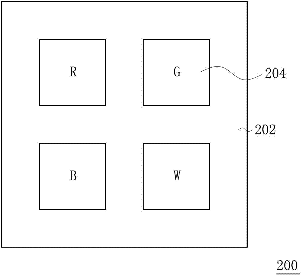
However, the degree of improvement of the light transmittance of the color filter 200 by using the white filter film W is still limited.

Method used


Image

  • Color filter and color display device using same
  • Color filter and color display device using same
  • Color filter and color display device using same

Examples


Embodiment Construction

[0046] In order to further explain the technical means and effects adopted by the present invention to achieve the intended purpose of the invention, the specific implementation of the color filter proposed according to the present invention and the color display device using it will be described below in conjunction with the accompanying drawings and preferred embodiments. , structure, feature and effect thereof, detailed description is as follows.

[0047] The following will take a color display device as an example to illustrate the application of the color filter of the present invention, but it is not intended to limit the present invention. Those skilled in the art should know that the color filter of the present invention can also be applied to other types of displays.

[0048] image 3 It is a schematic cross-sectional view of a color display device in an embodiment of the present invention. Please refer to image 3 , the color display device 300 includes an active ...


PUM


Abstract

A color filter includes a substrate and a plurality of pixel units. The substrate defines a plurality of pixel areas. Each pixel area has a plurality of first sub-pixel areas, and each first sub-pixel area has a first area and a second area. The pixel units are formed on the substrate corresponding to the pixel areas. Each pixel unit is disposed in a corresponding pixel area and includes a plurality of color subtractive filter films and a plurality of color additive filter films. The color subtractive filter films are disposed in the first areas of the first sub-pixel areas of the corresponding pixel area, and the color additive filter films are disposed in the second areas of the first sub-pixel areas of the corresponding pixel area. A color display device with the color filter is also disclosed. The color filter of the invention enhances the display brightness of the color display device and the color saturation during the display.

Description

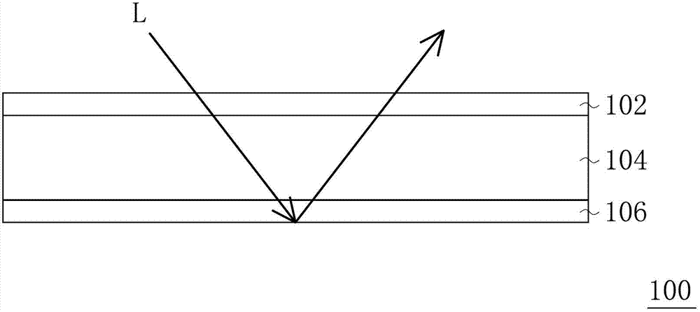
technical field [0001] The invention relates to a color filter, and in particular to a color filter with high transmittance and a color display device using the same. Background technique [0002] A reflective display uses reflected incident light as a light source for displaying images on the display. With the demand of consumers for products, the requirements of colorful and thin and light also arise at the historic moment. [0003] In the display, the color filter is a key component of color performance. figure 1 It is a schematic cross-sectional view of an existing color reflective display. Please refer to figure 1 , the color reflective display 100 includes a color filter 102 , a display medium layer 104 and an active element array substrate 106 . The light L outside the color reflective display 100 passes through the color filter 102 and the display medium layer 104 in sequence, and then is reflected by the active element array substrate 106 to pass through the dis...

Claims


Application Information

Patent Timeline
IPC IPC(8): G02B5/20G02F1/1335G02F1/167
CPCG02F1/133514G02B5/201G02F2201/52
Inventor 王以靓陈礼廷
Owner E INK HLDG INC
Learn More