2d/3d switching liquid crystal lens assembly

A liquid crystal lens and component technology, applied in the direction of optical components, optics, instruments, etc., can solve the problems of reducing costs, increasing the gap between liquid crystal layers of liquid crystal cells, increasing costs, etc., to achieve cost reduction, increase lens capacity, and reduce gaps Effect

Active Publication Date: 2016-12-21
SHENZHEN CHINA STAR OPTOELECTRONICS TECH CO LTD
View PDF4 Cites 0 Cited by
  • Summary
  • Abstract
  • Description
  • Claims
  • Application Information

AI Technical Summary

Problems solved by technology

However, increasing the thickness of the liquid crystal cell not only increases the liquid crystal layer gap (cell gap), but also undoubtedly increases the cost. Therefore, if a liquid crystal lens assembly for 2D / 3D image switching can be produced, there is no need to increase the thickness of the liquid crystal. Under the premise, the ability to focus can be improved, which will effectively reduce costs

Method used


Image

  • 2d/3d switching liquid crystal lens assembly
  • 2d/3d switching liquid crystal lens assembly
  • 2d/3d switching liquid crystal lens assembly

Examples


Embodiment Construction

[0025] The following descriptions of the various embodiments refer to the accompanying drawings to illustrate specific embodiments in which the present invention can be practiced. The directional terms mentioned in the present invention, such as "up", "down", "front", "back", "left", "right", "top", "bottom", "horizontal", "vertical", etc. , are for orientation only with reference to the attached drawings. Therefore, the directional terms used are used to illustrate and understand the present invention, but not to limit the present invention.

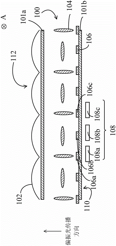
[0026] see figure 2 , figure 2 It is a schematic diagram of the cross-section and the alignment direction of liquid crystal molecules when the liquid crystal lens assembly according to the first embodiment of the present invention is applied in 3D mode. The liquid crystal lens assembly 100 sequentially includes several external lenses 102, a transparent substrate 101a, a liquid crystal layer 104, a transparent substrate 101b and se...


PUM


Abstract

A 2D / 3D switchable liquid crystal lens assembly (100) comprises, from a light output surface (112) to a light input surface (110) in sequence, a plurality of adjacently-arranged elongated convex lenses (102), a first transparent base plate (101a), a second transparent base plate (101b), a plurality of electrodes (106) arranged on the second transparent base plate (101b), and a liquid crystal layer (104) clamped between the first transparent base plate and the second transparent base plate. The plurality of electrodes (106) is used for controlling the arrangement direction of liquid crystal molecules of the liquid crystal layer (104) so as to adjust the refractive index of the liquid crystal molecules of the liquid crystal layer (104) to increase progressively or decrease progressively towards two sides relative to the center of at least one pixel (108), and used for controlling the advance direction of incident light and leading the passing incident light into one of the convex lenses (102).

Description

technical field [0001] The invention relates to a liquid crystal lens assembly, especially a 2D / 3D switching liquid crystal lens assembly with high lens power. Background technique [0002] Human beings perceive the image of the real world through the outlook seen by the eyes. The human brain will further form a so-called 3-dimensional (3-dimension, 3D) image based on the spatial distance difference between two different perspectives seen by the eyes. This spatial distance difference is called parallax (parallax). ). The so-called 3D display device is to simulate the field of view of different angles of human eyes, so that the left and right eyes receive two 2-dimensional (2-dimension, 2D) images with parallax, so that the human brain can obtain the different 2D images seen by the left and right eyes. After viewing the image, it can be perceived as a 3D image. [0003] The current 3D display devices are mainly divided into two categories, which are auto-stereoscopic displ...

Claims


Application Information

Patent Timeline
Patent Type & Authority Patents(China)
IPC IPC(8): G02F1/29G02F1/1343G02F1/1335G02B27/22
CPCG02F1/133526G02F1/134363G02F1/1393G02F1/29G02F1/294
Inventor 陈峙彣萧嘉强
Owner SHENZHEN CHINA STAR OPTOELECTRONICS TECH CO LTD
Why Eureka
Try Eureka