Automatic standby power source switching system

A technology of backup power supply and automatic input, which is applied in the direction of power network operating system integration, emergency power supply arrangement, information technology support system, etc., and can solve problems such as the inability to ensure stable power supply.

Inactive Publication Date: 2013-01-02
GUANGZHOU POWER SUPPLY CO LTD
View PDF4 Cites 17 Cited by
  • Summary
  • Abstract
  • Description
  • Claims
  • Application Information

AI Technical Summary

Problems solved by technology

[0004] Based on this, it is necessary to provide an automatic standby power supply system for the problem that the existing automatic standby power supply technology cannot ensure continuous and stable power supply.

Method used


Image

  • Automatic standby power source switching system
  • Automatic standby power source switching system
  • Automatic standby power source switching system

Examples


Embodiment 1

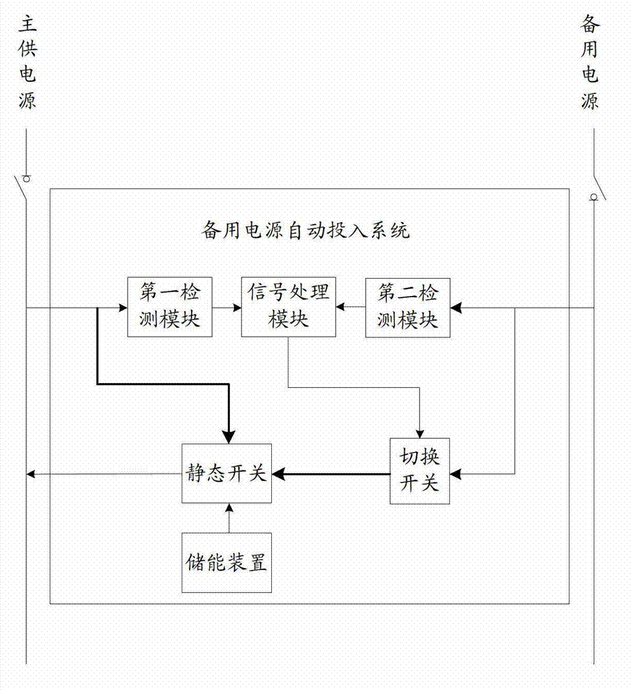
[0020] figure 1 It is a schematic structural diagram of the backup power supply automatic input system of embodiment one; it mainly includes the following components:

[0021] A first detection module, a second detection module, a signal processing module, a switch, a static switch and an energy storage device;

[0022] The first detection module is used to detect the current and voltage values ​​of the main power supply;

[0023] The second detection module is used to detect the voltage value of the backup power supply;

[0024] The signal processing module is configured to generate and output a switching signal to the switching switch according to preset parameters when the current and voltage values ​​of the main power supply are zero and the voltage value of the backup power supply is not zero;

[0025] The changeover switch is used to connect the busbar of the standby power supply according to the switchover signal;

[0026] The static switch is used to connect the bus...

Embodiment 2

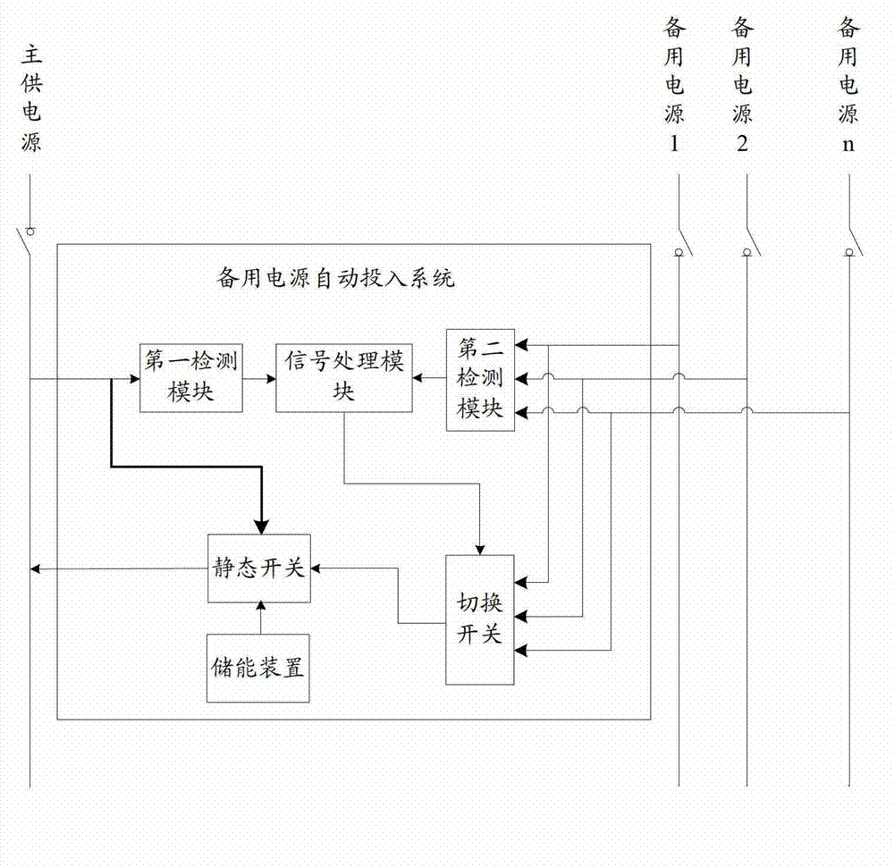
[0031] This embodiment is aimed at the application in the power supply system of multiple backup power supplies, figure 2 It is a schematic structural diagram of the backup power automatic input system of embodiment 2, including backup power 1~n;

[0032] The second detection module is used to respectively detect the voltage values ​​of multiple backup power sources;

[0033] The signal processing module is also used to select one backup power supply from multiple backup power supplies according to the preset parameters and the voltage value of the backup power supply, and generate a corresponding switching signal to output to the switch;

[0034] The switching switch is used to select and connect the bus bar of the corresponding backup power supply from multiple backup power supplies according to the switching signal.

[0035] Specifically, in the multi-channel backup power supply system, the backup power supply includes grid power supply, diesel generator, etc., the second...

Embodiment 3

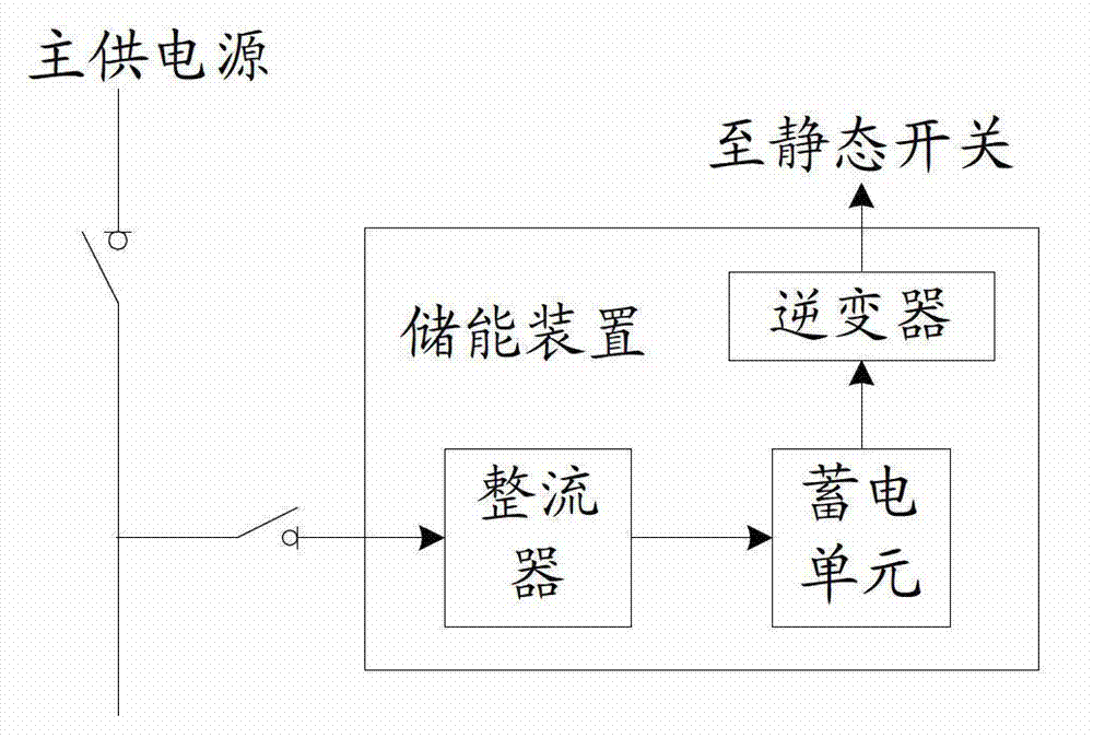
[0038] image 3 It is a schematic structural diagram of the energy storage device in Embodiment 3, which mainly includes: a rectifier, an electric storage unit, and an inverter connected in sequence; the rectifier is connected to the bus bar of the main power supply, and the inverter is connected to a static switch, wherein the storage The electric unit adopts a storage battery or an energy storage capacitor, etc.

[0039] Specifically, during normal power supply, the main power supply charges the battery or energy storage capacitor through the rectifier. When the main power supply fails, the battery or energy storage capacitor outputs DC power, and obtains AC power after passing through the inverter. The load on the main power supply is powered.

[0040] Other features of this embodiment are the same as those of Embodiment 1 or Embodiment 2, and will not be repeated here.


PUM


Abstract

The invention provides an automatic standby power source switching system which comprises a first detection module, a second detection module, a signal processing module, a selector switch, a static switch and an energy storage device. The first detection module is used for detecting current and voltage values of a main power source; the second detection module is used for detecting voltage value of a standby power source; the signal processing module is used for generating and outputting switching signals to the selector switch when the current and voltage values of the main power source are zero and the voltage value of the standby power source is not zero; the selector switch is used for switching on a bus of the standby bus according to the switching signals; the static switch is used for switching on the energy storage device to the bus of the main power source when the current and voltage values of the main power source are zero and switching an output end of the selector switch to the bus of the main power source when the voltage value of the standby power source is not zero; and the energy storage device is used for storing electric energy. By means of the automatic standby power source switching system, continuous and stable power supply of a power supply system is guaranteed, and especially, the special power supply requirements of sensitive devices are met, and safety in operation of the sensitive devices is guaranteed.

Description

technical field [0001] The invention relates to the technology of automatically putting in a backup power supply, in particular to a system for automatically putting in a backup power supply. Background technique [0002] With the high development of the tertiary industry in large cities, the manufacturing industry is also shifting to a high-tech value-added precision manufacturing model. More and more users, such as sports / performance venues, data centers, precision manufacturing and processing industries, have put forward higher requirements for power supply quality. [0003] At present, the backup power automatic input technology widely used in the power system is generally realized by using the backup power automatic input device (BZT) combined with related circuit breakers. However, the power supply standard of sensitive equipment is extremely high, and its power supply interruption or voltage temporary The drop even needs to be controlled within milliseconds, otherwis...

Claims


Application Information

Patent Timeline
Patent Type & Authority Applications(China)
IPC IPC(8): H02J9/06
CPCY02B70/30Y04S20/20
Inventor 吴国沛吴宇宁饶毅陈学东吴琼许继葵辛平野伍衡宁宇
Owner GUANGZHOU POWER SUPPLY CO LTD
Why Eureka
Try Eureka