Clock gating circuit used for double-edge trigger

A technology of double-edge triggering and clock gating, applied in the direction of electrical components, electric pulse generation, pulse generation, etc., can solve the problems that the clock gating circuit cannot realize the original design intention, the double-edge D flip-flop 50 circuit function error, etc., to achieve Solve the problem of circuit function error, the effect of normal function

Active Publication Date: 2013-01-02
RDA TECH
View PDF4 Cites 14 Cited by
  • Summary
  • Abstract
  • Description
  • Claims
  • Application Information

AI Technical Summary

Problems solved by technology

When using the latch 40 and the AND gate 30 to gate the clock control signal gclk of the double-edge D flip-flop 50, although it overcomes the problem caused by the enable signal en being in the high level state or the low level state of the clock signal clk The glitch phenomenon of the clock control signal gclk caused by instability, but the extra falling edge of the clock control signal gclk will still cause the circuit function error of the double-edge D flip-flop 50
[0015] It can be seen that for the double-edge trigger circuit, the traditional clock gating circuit can no longer realize the original design intention.

Method used


Image

  • Clock gating circuit used for double-edge trigger
  • Clock gating circuit used for double-edge trigger
  • Clock gating circuit used for double-edge trigger

Examples


Embodiment Construction

[0039] The applicant believes that a clock gating circuit that meets the application requirements of a double-edge trigger should meet the following requirements:

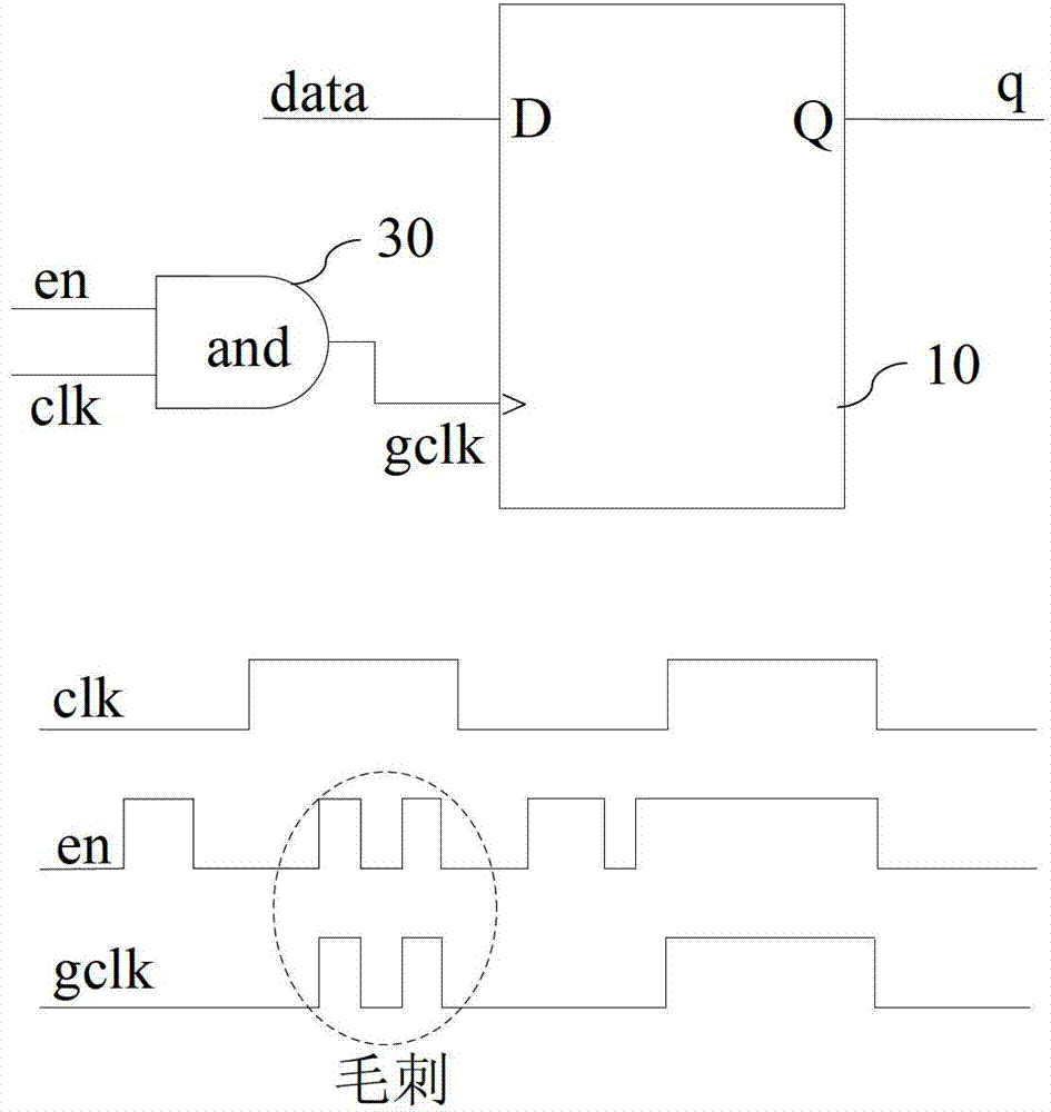
[0040] 1. When the enable signal en is unstable in the high-level state or low-level state of the clock signal clk, the clock control signal gclk serving as the clock input of the double-edge trigger should not have glitches.

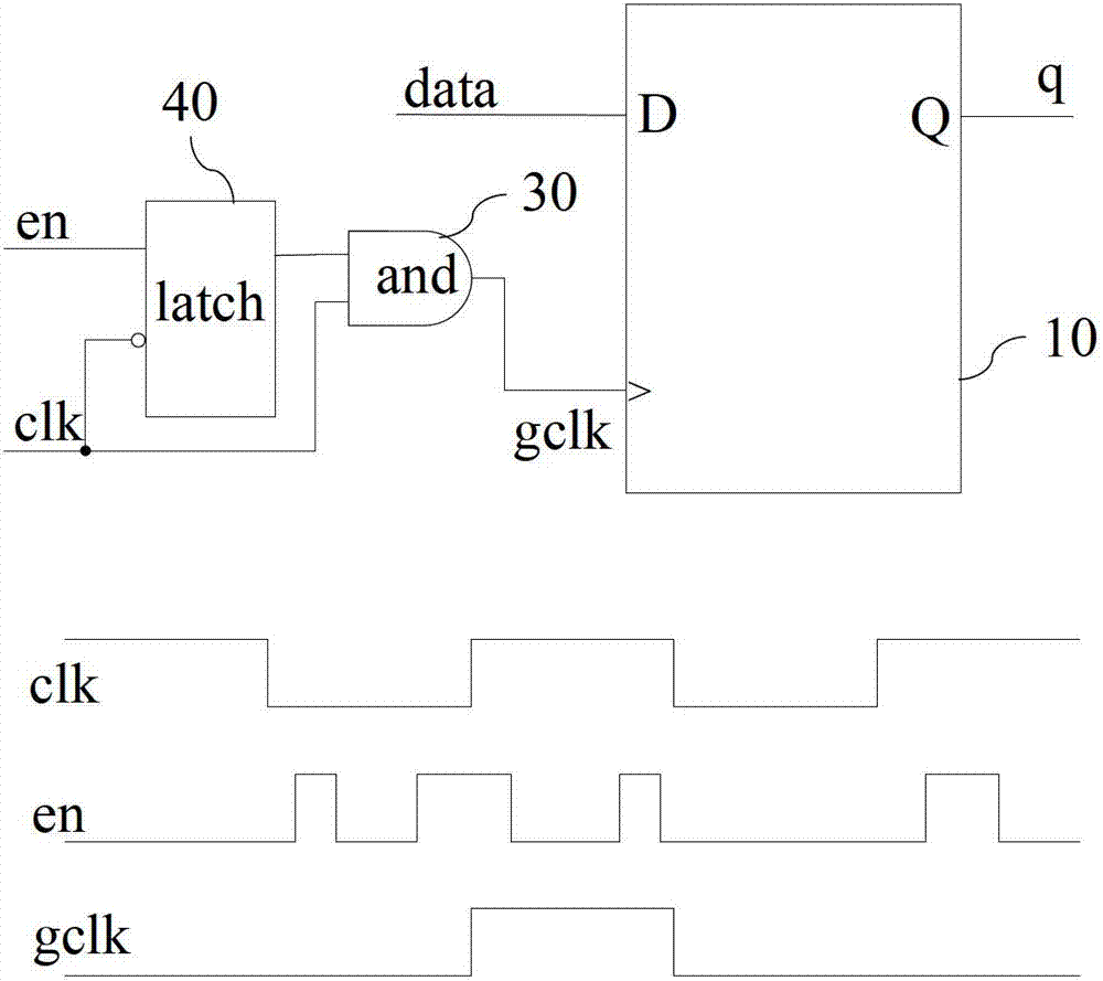
[0041] 2. When the enable signal en is at low level, the clock control signal gclk remains in its original state, and there is no change of rising edge or falling edge. At this time, the double-edge trigger stops working; when the enable signal en is at high level, the clock control signal The signal gclk flips along with the high and low level flips of the clock signal clk, and the double-edge trigger works normally at this time.

[0042] 3. Ensure that the duty cycle of the clock control signal gclk is consistent with that of the clock signal clk when the clock control signal gclk is worki...


PUM


Abstract

The invention discloses a clock gating circuit used for a double-edge trigger. The clock gating circuit is a logic unit, wherein the logic unit has four input ends and two output ends including a first input end, a second input end, a third input end, a fourth input end, a first output end and a second output end, wherein the first input end is connected with the first output end, the second input end is connected with the second output end, the third input end is used for receiving an enable signal, the fourth input end is used for receiving a clock signal, the first output end is used for outputting and receiving a clock control signal of the double-edge trigger of a clock gating; and the second output end is used for outputting a inversion signal from the first output end. On a rising edge and a descending edge of the clock signal, when the enable signal is in low level, the first output end is used for copying the first input end; and on the rising edge and the descending edge of the clock signal, when the enable signal is in high level, the first output end is used for copying the second output end. The clock gating circuit can be directly applied in the design of a digital circuit containing the double-edge trigger and is normal in function, thereby effectively solving the problems of burrs and circuit function errors of the traditional clock gating unit.

Description

technical field [0001] The present application relates to a clock gating circuit, in particular to a clock gating circuit suitable for double-edge triggers. Background technique [0002] The power consumption of digital circuits is composed of two parts, one is static power consumption, which is usually expressed as the leakage current of electronic circuits, and the control of this part of power consumption mainly depends on the production process and materials used; the other is dynamic power consumption, which affects the There are many factors for partial power consumption, such as the way the circuit is designed, the complexity of the circuit, and the operating clock frequency. [0003] In digital circuits, the clock signal is often the signal with the largest fanout and the widest distribution in the system. If no control is added, the clock signal will always flip regardless of whether the input signal changes, causing unnecessary power loss. In a typical digital ci...

Claims


Application Information

Patent Timeline
Patent Type & Authority Applications(China)
IPC IPC(8): H03K3/013
Inventor 郑松魏述然张亮张标谢晓娟
Owner RDA TECH
Why Eureka
Try Eureka