A key detection circuit
A technology for detecting circuits and buttons, applied in the direction of dynamic coding, etc., can solve problems such as misjudgment and recognition into others, and achieve the effects of good system robustness, low production cost, and simple structure
- Summary
- Abstract
- Description
- Claims
- Application Information
AI Technical Summary
Problems solved by technology
Method used
Image
Examples
Embodiment 1
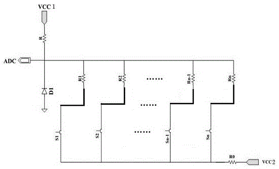
[0020] Example 1, such as figure 1 As shown, a button detection circuit includes a pull-up resistor R, N buttons, and N voltage divider resistors (R 1 , R 2 ,...,R n ), N is a natural number, the N buttons are respectively connected in series with the N voltage dividing resistors one by one, and then connected in parallel. One end of the parallel circuit is grounded, and the other end is connected to the power supply VCC through the pull-up resistor R. The pull resistance R is connected to the parallel terminal of the power supply VCC and is connected to the signal processing unit as the signal output terminal; the voltage divider resistance R 1 , R 2 ,...,R n The resistance value satisfies: R 1 2 n ; In the button detection circuit, several buttons are pressed at the same time, and among the pressed buttons, the voltage dividing resistor connected in series is at least R i , the resistance value is less than R i and the resistance value closest to R i The voltage divi...
Embodiment 2
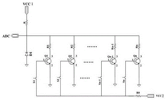
[0022] Example 2, such as figure 2 As shown, a button detection circuit includes a pull-up resistor R and N buttons, and N voltage divider resistors R 1 , R 2 ,...,R n , N triodes Q1, Q2, ..., QN, N is a natural number, the emitters of the N triodes are all grounded, the collectors are respectively connected to N voltage dividing resistors, the bases of the triodes are respectively connected to N buttons, N buttons The other ends are connected to the resistor R0 and connected to the power supply VCC through the resistor R0; the other ends of the N voltage divider resistors are connected in parallel to the power supply VCC through the pull-up resistor R. Power supply VCC; the voltage divider resistor R 1 , R 2 ,...,R n The resistance value satisfies: R 1 2 n ; In the button detection circuit, several buttons are pressed, and among the pressed buttons, the voltage dividing resistor connected in series is at least R i , the resistance value is less than R i and the resis...
PUM
 Abstract
Description
Claims
Application Information
 - R&D
- Intellectual Property
- Life Sciences
- Materials
- Tech Scout
- Unparalleled Data Quality
- Higher Quality Content
- 60% Fewer Hallucinations
Browse by: Latest US Patents, China's latest patents, Technical Efficacy Thesaurus, Application Domain, Technology Topic, Popular Technical Reports.
© 2025 PatSnap. All rights reserved.Legal|Privacy policy|Modern Slavery Act Transparency Statement|Sitemap|About US| Contact US: help@patsnap.com


