
Oil-pressure chain rivet head machine

A technology of riveting head machine and chain, applied in the direction of metal chain, etc., can solve the problems of increasing the size, the chain riveting head cannot meet people's environment, and the riveting head machine has no flexibility, etc., and achieves the effect of preventing leakage riveting.

Active Publication Date: 2013-01-09
SUZHOU CHUNMENG INTELLIGENT TECHNOLOGY CO LTD
View PDF11 Cites 21 Cited by
  • Summary
  • Abstract
  • Description
  • Claims
  • Application Information

AI Technical Summary

Problems solved by technology

However, this kind of riveting head machine can only adapt to the riveting heads of small and medium chains. If a larger chain needs to be riveted, the up and down movement range of the riveting head frame needs to be increased, the pitch of the chain is increased, and the size of the feed plate needs to be enlarged. Whether it is the cam that drives the riveting head frame or the driving cam that drives the mobile version, the specifications need to be greatly increased, and it is inevitable to design a large and complex riveting head machine.
Moreover, such a riveting machine has no flexibility at all. The 4 riveting dies or 2 riveting dies connected to the riveting head frame can only be moved up and down with the riveting head frame, and all of them are passively chamfered against the chain. head, instead of four-sided riveting head and two-sided riveting head for the chain according to the needs
And it is impossible to realize the skipping riveting head. In the subsequent chain cutting process, because the pin shaft of the chain with the cut off head is riveted, it cannot be ejected smoothly by the cutting device, causing damage to the relevant chain links, so as to manufacture a 50 For example, for every 50-section chain, one section of chain will be lost in the subsequent cutting process, resulting in great waste
[0004] To sum up, in the current chain manufacturing industry, chain riveting heads are far from meeting people's requirements for the environment, chain quality, and low production loss.

Method used

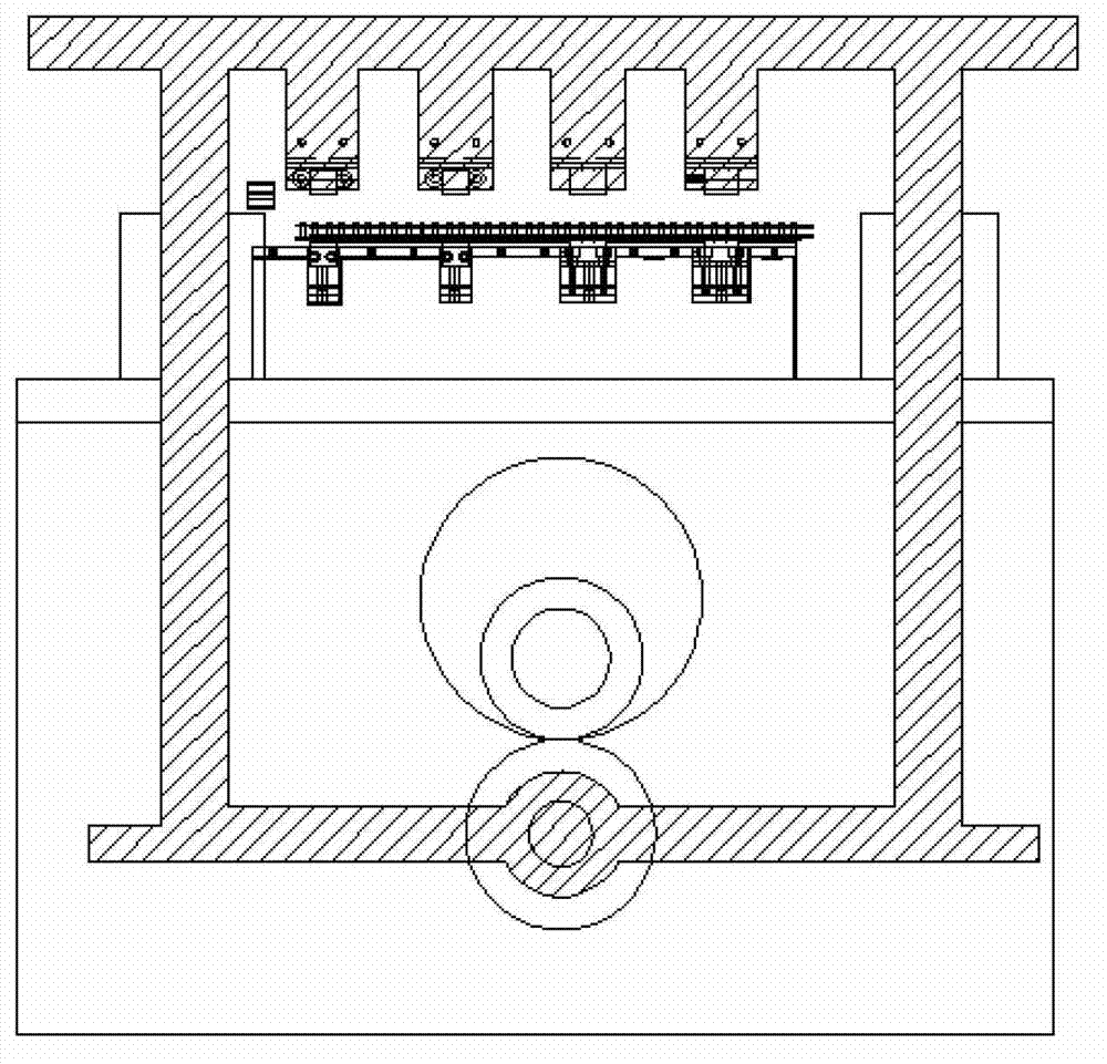
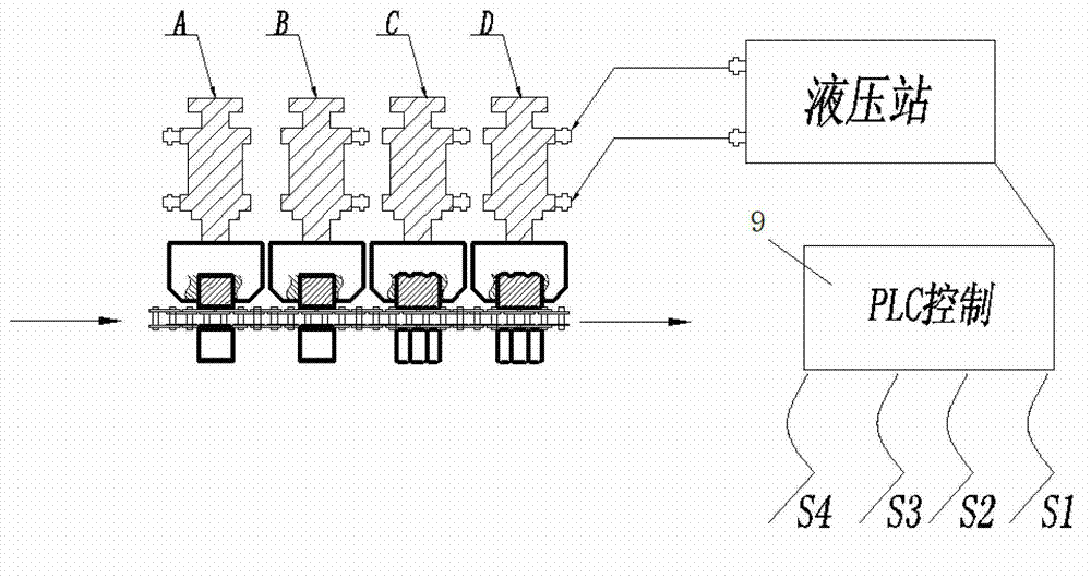

Image

  • Oil-pressure chain rivet head machine
  • Oil-pressure chain rivet head machine
  • Oil-pressure chain rivet head machine

Examples


Embodiment Construction

[0035] In order to make the objectives, technical solutions, and advantages of the present invention clearer, the following further describes the present invention in detail with reference to the accompanying drawings and embodiments. It should be understood that the specific embodiments described here are only used to explain the present invention, but not to limit the present invention.

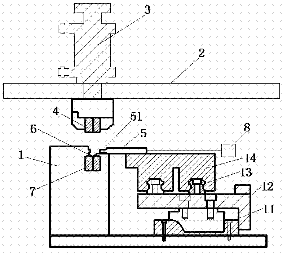
[0036] figure 2 Is a schematic diagram of the structure of the present invention, such as figure 2 As shown, a hydraulic chain riveting machine includes a worktable 1 and a support frame 2. The support frame 2 is provided with a hydraulic cylinder 3, and an upper riveting die 4 is connected below the hydraulic cylinder 3; A chain channel 6 is provided on the table 1, and a lower riveting head die 7 is provided at a position corresponding to the upper riveting head die 4 in the chain channel 6; a moving plate 5 is also provided on the worktable 1 and the moving plate 5 The side close to the c...


PUM


Abstract

The invention provides an oil-pressure chain rivet head machine, comprising a worktable and a supporting frame, wherein the supporting frame is provided with a hydraulic cylinder and an upper rivet head die is connected below the hydraulic cylinder; a chain channel is arranged on the worktable; the chain channel is internally provided with a lower rivet head die at a position corresponding to the upper rivet head die; the worktable is further provided with a movable plate; and one side of the movable plate, which is close to the chain channel, is in a saw-tooth structure, and the movable plate is connected with a movable plate driving device. A PLC (Programmable Logic Controller) control device is combined with an oil-pressure system so as to realize full-automatic, intelligent and multifunctional rivet heads which can be a four-faced rivet head and a double-faced rivet head; and a certain section of a whole chain is not subjected to the rivet head so as to be convenient for post-period detection and cutting.

Description

Technical field [0001] The invention relates to the chain manufacturing industry, in particular to a hydraulic chain riveting machine. Background technique [0002] In the chain manufacturing industry, the assembled chain must be riveted. However, the current chain riveting equipment adopts the principle of mechanical linkage, and the design of the riveting machine is complicated in structure and bulky. The strength and speed of the mechanical punching riveting head are completely impossible. The quality of the riveting head cannot be adjusted to the best condition, and all the chain links are riveted, and the skipping function cannot be realized, which causes a lot of waste. In addition, the noise of the mechanical stamping is large, which can no longer meet the requirements of the construction of economical and environmentally friendly The requirements of the society, the transformation of equipment in the chain manufacturing industry has been promoted to the direction of natio...

Claims


Application Information

Patent Timeline
Patent Type & Authority Applications(China)
IPC IPC(8): B21L9/06
CPCB21L9/06
Inventor 何汉朝何治富刘刚
Owner SUZHOU CHUNMENG INTELLIGENT TECHNOLOGY CO LTD
Learn More