Electric laundry rack

A drying rack and electric technology, applied in the field of drying racks, can solve problems such as easy failure, large space occupation, and inability to automatically limit positions, and achieve the effects of preventing mechanical failures, stable work, and convenient use

Active Publication Date: 2013-01-09
苏州市沃旗电器有限公司
View PDF4 Cites 15 Cited by
  • Summary
  • Abstract
  • Description
  • Claims
  • Application Information

AI Technical Summary

Problems solved by technology

[0002] At present, there are many kinds of drying racks used by people, including simple non-adjustable drying racks, which occupy a large space and cannot meet the diverse requirements of people for drying clothes. Disadvantages of failure, at the same time, it cannot automatically limit the position, which is easy to cause mechanical failure

Method used


Image

  • Electric laundry rack
  • Electric laundry rack
  • Electric laundry rack

Examples


Embodiment 1

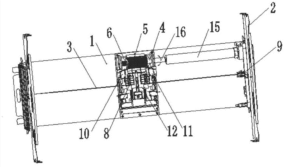
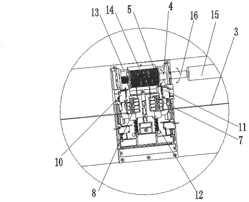
[0020] Such as figure 1 and figure 2 As shown, a kind of electric drying rack of the present invention, support 1, driving assembly, winding assembly, suspension bridge connecting rod assembly 2 and steel wire 3, driving assembly, winding assembly are arranged on the support, driving assembly and winding assembly drive connection , the suspension bridge link assembly 2 is arranged at both ends of the bracket 1; the winding assembly includes a rotating shaft 4, a winding wheel 5, a screw rod 6, a slider pulley 7, a sliding block 8 and a side wheel 9, the rotating shaft 4 is connected with the driving assembly, and the winding One end of wheel 5 is connected with rotating shaft 4, and the other end of winding wheel 5 is connected with screw rod 6, and slide block 8 is arranged on one side of winding wheel 5, and slide block pulley 7 is arranged in slide block 8, and edge wheel 9 is arranged on One side of the suspension bridge connecting rod assembly 2; one end of the steel wi...

Embodiment 2

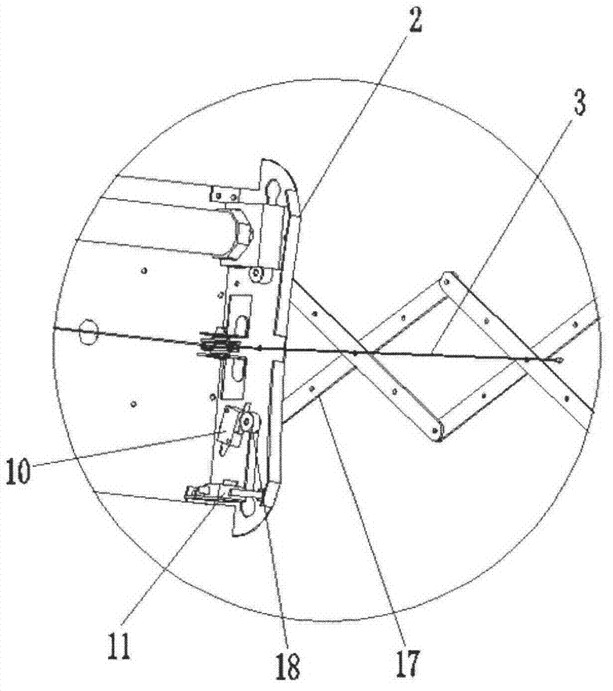
[0029] Such as image 3 and Figure 4 As shown, limit switches are also included, including an upper limit switch 10 and a lower limit switch 11. The limit switch is arranged at the connection between the bracket 1 and the suspension bridge link assembly 2, and the upper limit switch 10 is arranged below the lower limit switch 11.

[0030] When the steel wire 3 drives the suspension bridge connecting rod assembly 2 to move, the suspension bridge connecting rod assembly 2 drives the cross bracket 17 to expand and contract, and the end of the cross bracket 17 is provided with a pulley switch 18. When the cross bracket 17 is telescopic, the pulley switch 18 slides left and right in the guide groove. When touching the lower limit switch 11 on the suspension bridge link assembly 2, the cross bracket 17 stops stretching. When starting again, the cross bracket can only move upward.

[0031] When the cross bracket 17 rises to the highest point, the distance between the two adjacent c...


PUM


Abstract

The invention discloses an electric laundry rack which comprises a bracket, a driving component, a winding component, hanging bridge connecting rod components and a steel wire. The driving component and the winding component are arranged on the support and connected in a driving mode; the hanging bridge connecting rod components are arranged at two ends of the support; the winding component comprises a spindle, a reel, a screw, a slider pulley, a slider and a cincture, wherein the spindle is connected with the driving component, one end of the reel is connected with the spindle, the other end of the reel is connected with the screw, the slider is arranged on one side of the reel, the slider pulley is arranged in the slider, and the cincture is arranged on one side of one hanging bridge connecting rod component; and one end of the steel wire is connected with the reel, the other end is connected with the other hanging bridge connecting rod component, and the steel wire is wound on the slider pulley and the cincture. Through the mode, a motor is used for supplying power for the rack, the rack is controlled to stretch and contract, the operation is stable, automatic limit is performed when the rack is in place, mechanical failures due to resistance meeting can be prevented effectively, and the rack is convenient to use.

Description

technical field [0001] The invention relates to a clothes drying rack, in particular to an electric clothes drying rack. Background technique [0002] At present, there are many kinds of drying racks used by people, including simple non-adjustable drying racks, which occupy a large space and cannot meet the diverse requirements of people for drying clothes. The disadvantage of failure is that it cannot automatically limit the position at the same time, which is easy to cause mechanical failure. Contents of the invention [0003] In order to solve the above-mentioned technical problems, the object of the present invention is to provide an electric clothes drying rack, which uses a motor to provide power, controls the expansion and contraction of the clothes drying rack, works smoothly, automatically limits the position when it is in place, effectively prevents mechanical failures caused by obstacles, and has a simple structure. No noise, easy to use. [0004] In order to ...

Claims


Application Information

Patent Timeline
Patent Type & Authority Applications(China)
IPC IPC(8): D06F57/12
Inventor 陈位丰
Owner 苏州市沃旗电器有限公司
Why Eureka
Try Eureka