High-pressure main throttle valve apparatus of steam turbine

A main steam valve and steam turbine technology, applied in mechanical equipment, engine components, machines/engines, etc., can solve the problems of easy bending of the valve stem, large closing resistance of the main steam valve, and long closing time, so as to avoid closing time Effect of too long, reduced closing resistance, reduced possibility

Active Publication Date: 2013-01-09
CHINA SHENHUA ENERGY CO LTD +2
View PDF6 Cites 6 Cited by
  • Summary
  • Abstract
  • Description
  • Claims
  • Application Information

AI Technical Summary

Problems solved by technology

[0006] In actual operation, emergency shutdown often causes the main steam valve to close for too long
Especially in the state of high load, the phenomenon of too long shutdown time is more serious
After inspection, it was found that the main reason for the too long closing time of the main steam valve was that the spring seat 13 in the spring mechanism 20 was stressed and the valve stem of the main steam valve was easy to bend, which resulted in a larger closing resistance of the main steam valve.
[0007] Additionally, from Figure 1B It can be seen from the figure that in the process of switching the high-pressure main steam valve, the movement of the joint between the lever 32, the piston rod 31 and the guide rod 15 can be regarded as an arc movement, and this arc movement will inevitably cause the valve stem 21 and the piston rod to 31 is subject to a large lateral force, which increases the resistance of the high-pressure main steam valve to close
[0008] The above situations will cause the problem that the main steam valve closes for too long, and due to the bending of the valve stem and the presence of lateral force, it is easy to cause interference between the guide rod, the lever and the piston rod during the opening and closing of the main steam valve, resulting in the piston cylinder Oil leakage, etc., pose a serious threat to the safe and reliable operation of the steam turbine unit

Method used


Image

  • High-pressure main throttle valve apparatus of steam turbine
  • High-pressure main throttle valve apparatus of steam turbine
  • High-pressure main throttle valve apparatus of steam turbine

Examples


Embodiment Construction

[0041] Specific embodiments of the present invention will be described in detail below in conjunction with the accompanying drawings. It should be understood that the specific embodiments described here are only used to illustrate and explain the present invention, and are not intended to limit the present invention.

[0042] In the present invention, in the case of no contrary description, the used orientation words such as "inner and outer" usually refer to the center line of the housing of the spring mechanism, which is relatively close to the center line of the housing. "inner" and "outer" which is relatively far away from the center line of the shell.

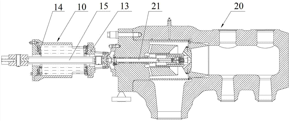
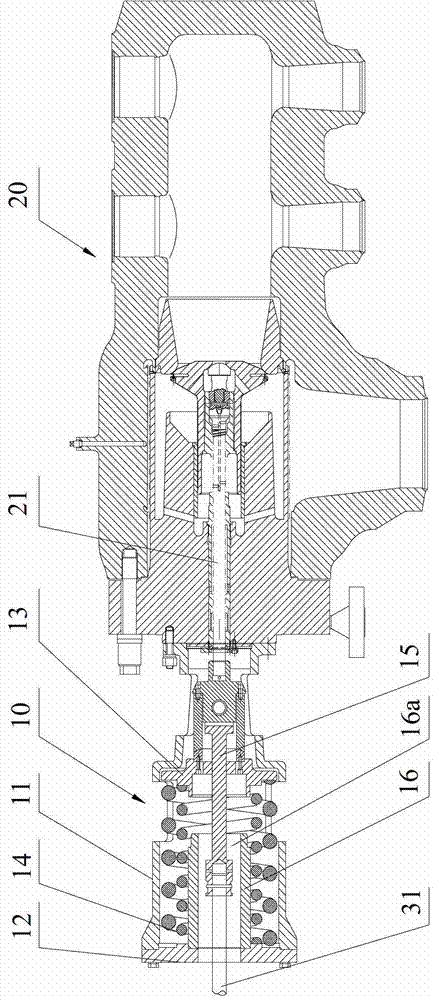
[0043] As mentioned above, the existing main valve device often has the problem of too long closing time during emergency shutdown. After inspection and verification, it is found that the main reason for the long closing time of the main steam valve is that the valve stem 21 of the main steam valve 20 bears the gravity of...


PUM


Abstract

The invention discloses a high-pressure main throttle valve apparatus of a steam turbine. The high-pressure main throttle valve apparatus comprises a main throttle valve (20) and a spring mechanism (10), wherein the spring mechanism (10) comprises a housing (11), a spring seat (13), a spring (14) and a guide rod (15), wherein the housing (11) is fixed on a main stop valve (11), an end cover (12) is arranged on one end of the spring, the spring seat (13) is movably mounted in the housing along the axial direction, two ends of the spring (14) are respectively mounted on the end cover and the spring seat and respectively apply an elastic force onto the end cover and the spring seat, the guide rod (15) is connected with a valve rod (21) of the main stop valve in the housing, a guide cylinder (16) is fixed in the housing, the spring is sleeved on the guide cylinder (16), the guide rod can move in a hollow cavity (16a) of the guide cylinder, and the spring seat is supported on the guide cylinder (16) when the main stop valve is opened. According to the high-pressure main throttle valve apparatus of the steam turbine, the gravities of the spring seat and the spring are borne by the guide cylinder, the gravity borne by the valve rod is reduced, and the problem that closing time of the main stop valve is too long is avoided.

Description

technical field [0001] The invention relates to the field of thermal power generation, in particular to a high-pressure main valve device for a turbine wheel. Background technique [0002] In the steam turbine, the function of the high-pressure main steam valve is to block the incoming steam urgently when necessary; when the steam turbine unit is started, the high-pressure main steam valve has the function of adjusting the speed. [0003] A horizontal high-pressure main steam valve is usually used in existing steam turbines, wherein the main steam valve 20 is usually opened by an oil motor and closed by a spring mechanism. Specifically, such as Figure 1A and Figure 1B As shown, the piston rod 31 of the piston cylinder 30 is connected to the guide rod 15 in the spring mechanism 10 through the lever 32 , and the guide rod 15 is connected to the valve rod 21 of the main steam valve 20 . Wherein the piston rod 31 is perpendicular to the lever 32, and the guide rod 15 is conn...

Claims


Application Information

Patent Timeline
Patent Type & Authority Applications(China)
IPC IPC(8): F01D17/10
Inventor 甘超齐李世涛张俊杰王学成汪勇刚李春光
Owner CHINA SHENHUA ENERGY CO LTD
Why Eureka
Try Eureka