Duel-voltage, duel-maintenance and duel-follow current driving circuit

A drive circuit and power drive circuit technology, applied in the direction of engine components, valve details, valve operation/release devices, etc., can solve problems such as difficult to meet requirements, slow speed, and unsatisfactory high-speed solenoid valve applications

Active Publication Date: 2013-01-09
GUIZHOU HONGLIN MACHINERY
View PDF5 Cites 5 Cited by
  • Summary
  • Abstract
  • Description
  • Claims
  • Application Information

AI Technical Summary

Problems solved by technology

[0002] At present, the solenoid valve driving industry generally uses the pulse width modulation (PWM) method to drive the solenoid valve. Its common driving form can solve most of the driving problems for general applications, but for high-speed solenoid valve applications It is not ideal, mainly in the slow response speed
In order to improve the response speed of the solenoid valve, the industry has proposed a dual-voltage PWM driving method within the scope of the PWM method, but this dual-voltage PWM driving method is still difficult to meet the requirements

Method used


Image

  • Duel-voltage, duel-maintenance and duel-follow current driving circuit
  • Duel-voltage, duel-maintenance and duel-follow current driving circuit
  • Duel-voltage, duel-maintenance and duel-follow current driving circuit

Examples


Embodiment Construction

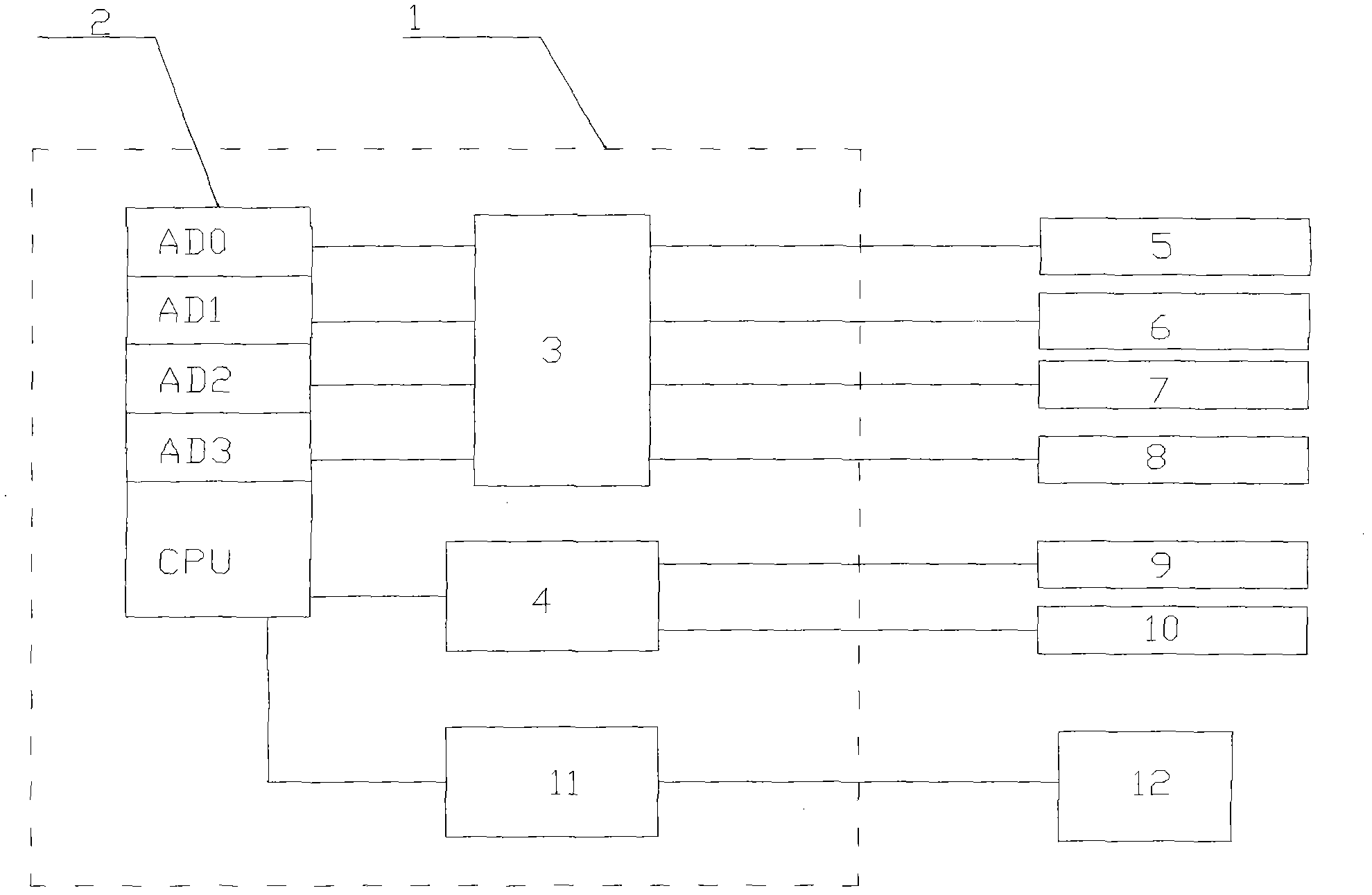
[0014] Embodiments of the invention: figure 1 It is a schematic diagram of a dual-voltage, dual-maintenance, and dual-freewheel drive circuit according to the present invention, which includes a driver 1 and a solenoid valve 12; it is characterized in that the signal input end of the driver 1 is composed of six adjustment knobs, which are respectively PWM duty cycle Adjustment knob 5, PWM frequency adjustment knob 6, delay time adjustment knob 7, excitation time adjustment knob 8, high maintenance current adjustment knob 9, high / low maintenance current adjustment knob 10; the signal output end of the driver 1 is connected to the solenoid valve 12.

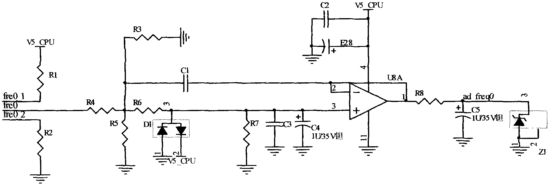
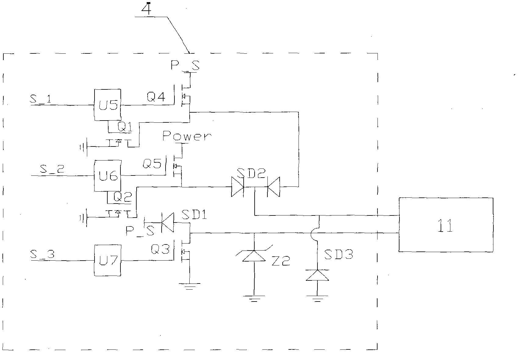
[0015] CPU2, input circuit 3, current comparison circuit 4 and power drive circuit 11 are provided in the driver 1; the signals of PWM duty ratio adjustment knob 5, PWM frequency adjustment knob 6, delay time adjustment knob 7 and excitation time knob 8 are input to Input circuit 3, input circuit 3 is connected to the digital-to-a...


PUM


Abstract

The invention discloses a duel-voltage, duel-maintenance and duel-follow current driving circuit. A signal input end of a driver comprises six adjusting knobs, and a signal output end of the driver is connected with an electromagnetic valve; a CPU (Central Processing Unit), an input circuit, a current comparison circuit and a power driving circuit are arranged in the driver; all the adjusting knobs are connected with an input circuit which is connected to digital-to-analogue conversion ports (AD0-AD3) of the CPU; the CPU outputs an excitation signal, a high-side driving signal and a low-side driving signal to a signal input end of the power driving circuit after calculating the corresponding time through AD conversion; signals of a high-maintenance current adjusting knob and a high/low-maintenance current adjusting knob are input to the current comparison circuit and are processed by the current comparison circuit to be output and connected to the high-side driving signal input end of the power driving circuit; and a signal output end of the power driving circuit is connected with the electromagnetic valve.

Description

technical field [0001] The invention relates to a solenoid valve driving circuit, which belongs to the technical field of solenoid valve driving. Background technique [0002] At present, the solenoid valve driving industry generally uses the pulse width modulation (PWM) method to drive the solenoid valve. Its common driving form can solve most of the driving problems for general applications, but for high-speed solenoid valve applications It seems not ideal, mainly in the slow response speed. In order to improve the response speed of the solenoid valve, the industry has proposed a dual-voltage PWM driving method within the scope of the PWM method, but this dual-voltage PWM driving method is still difficult to meet the requirements. Contents of the invention [0003] The purpose of the present invention is to: improve the driving method on the basis of dual voltages, adopt double maintenance, double freewheeling drive circuit, i.e. high current, low current maintenance, u...

Claims


Application Information

Patent Timeline
Patent Type & Authority Applications(China)
IPC IPC(8): F16K31/06
Inventor 苗建中敖成丽张黔飞
Owner GUIZHOU HONGLIN MACHINERY
Why Eureka
Try Eureka