
Three-dimensional imaging device

A three-dimensional imaging and driving device technology, applied in optics, instruments, camera bodies, etc., can solve the problems of unsatisfactory, unusable, and shooting 3D image effects, and achieve rich expressions.

Inactive Publication Date: 2013-01-09
DANIC INDAL
View PDF5 Cites 6 Cited by
  • Summary
  • Abstract
  • Description
  • Claims
  • Application Information

AI Technical Summary

Problems solved by technology

However, since the shooting angle of the lens is fixed, general 3D cameras are all shooting in the "background" and cannot use "foreground" shooting; and when shooting, due to the limitation of the shooting distance, the effect of the captured 3D picture will be caused. poor performance

Method used


Image

  • Three-dimensional imaging device
  • Three-dimensional imaging device
  • Three-dimensional imaging device

Examples


Embodiment Construction

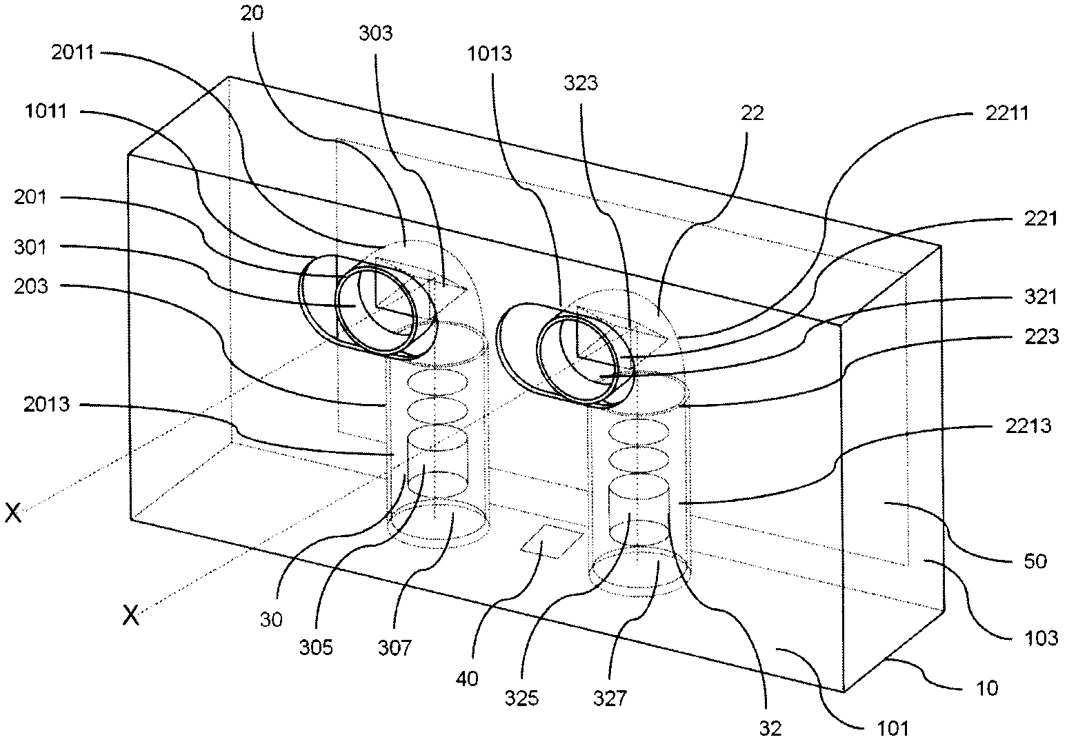
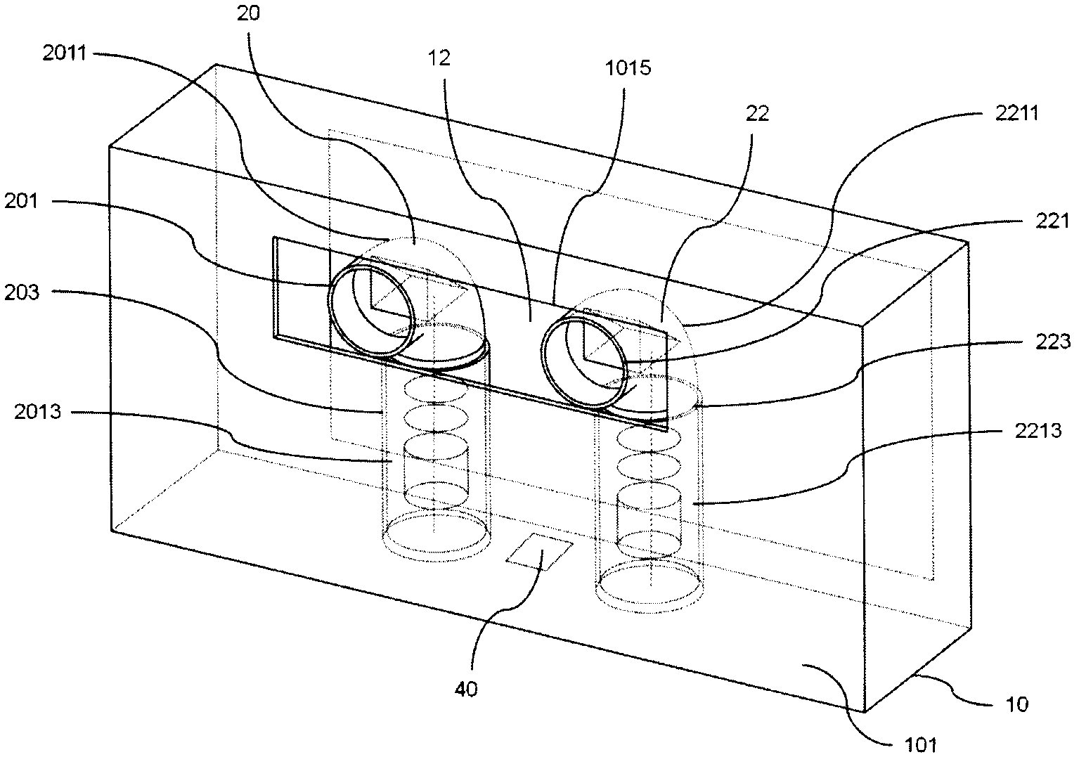
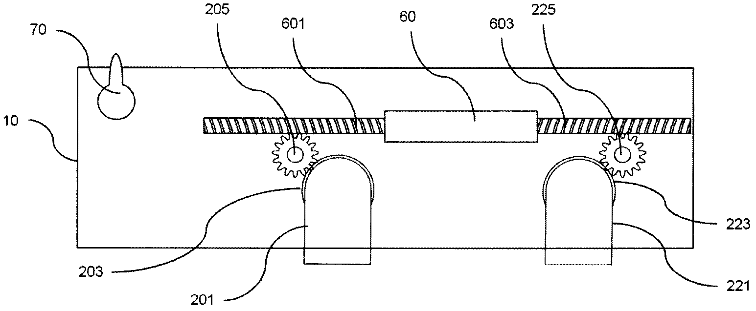
[0022] Since the present invention discloses a 3D imaging device, some of the lens modules, zoom modules and photosensitive elements related to the imaging device used in it are achieved by using existing technologies, so in the following description, a complete description is not given. . In addition, the courts in the following texts are not completely drawn according to the actual relevant dimensions, and their function is only to express the schematic diagram related to the features of the present invention.

[0023] First, see figure 1 , is a schematic perspective view of the 3D imaging device of the present invention. Such as figure 1 As shown, the 3D imaging device includes: a body 10 having a front panel 101 and a rear panel 103 opposite to the front panel 101, and the front panel 101 has a first opening 1011 and a second opening 1013 A first rotating module 20 and a second rotating module 22 are configured in the fuselage 10, and the first rotating module 20 and th...


PUM


Abstract

The invention relates to a three-dimensional imaging device capable of regulating shooting angles of two shooting lens. By a driving device in the three-dimensional imaging device, the shooting angles of two shooting lens are regulated to be crossed in front or behind a shot object, so that a shot three-dimensional picture generates a foreground or background three-dimensional effect, the effect of the three-dimensional picture can be more diversified and the manifestation mode of the three-dimensional picture is richer.

Description

technical field [0001] The present invention relates to a device with a three-dimensional (3D) display function, in particular to a three-dimensional imaging image capture device, such as a camera and video camera. Background technique [0002] In recent years, due to the popularity of three-dimensional (or called 3D / Three Dimensional; hereinafter, 3D means three-dimensional) movies, people's demand for 3D movies is increasing day by day. Relatively, 3D products have also shifted from movies to the LCD industry. First of all, why human beings can see the depth through vision and feel the three-dimensional sense, the most important point is that the vision of the human eye can feel the depth, that is, "depth perception (depth perception)"; The relative position in the three-dimensional space can be judged only after the information is obtained. Since the positions of the two eyes of a person are different, the distance between the two eyes of an average person is about 5 to...

Claims


Application Information

Patent Timeline
IPC IPC(8): G03B35/08G03B17/02
Inventor 陈振台陈文钦丁进兴杜凤榜余冠兴
Owner DANIC INDAL
Learn More