
Optical fiber display light source structure and optical fiber display device

A technology for display devices and optical fibers, which is applied in the directions of optical fiber light guides, identification devices, lighting devices, etc., can solve the problems of inability to meet the requirements of high brightness and high definition of image display, difficult image color display, affecting display effects, etc. Replacing the backlight source, realizing the effect of color display and short response time

Inactive Publication Date: 2013-01-09
BOE TECH GRP CO LTD
View PDF4 Cites 8 Cited by
  • Summary
  • Abstract
  • Description
  • Claims
  • Application Information

AI Technical Summary

Problems solved by technology

Due to the long distance between the light source and the light incident surface of the optical fiber, most of the light emitted by the light source cannot be vertically incident on the cross-section of the optical fiber, which cannot meet the high brightness and high definition of today's image display. Degree Requirements
Furthermore, the light source used in the prior art is an incandescent bulb, so when the display screen is made large enough, it will also affect the display effect.
In addition, in terms of realizing color, the optical fiber display device in the prior art is mainly realized by coating the light-emitting end of the optical fiber with color paint, and it is difficult to clearly realize the color display of the image.

Method used


Image

  • Optical fiber display light source structure and optical fiber display device
  • Optical fiber display light source structure and optical fiber display device

Examples


Embodiment 1

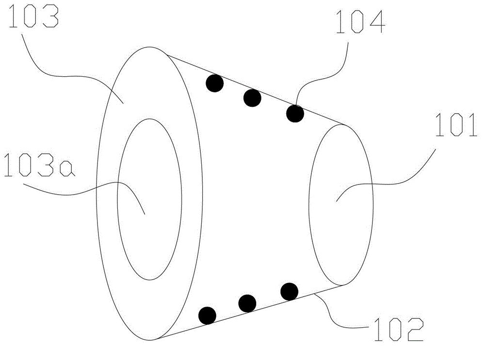
[0025] Such as figure 1 As shown, this embodiment describes a fiber optic display light source structure 1, including a circular light source 101. The fiber optic display light source structure 1 is a hollow truncated conical structure, and the upper bottom, side surfaces and lower bottom surfaces of the hollow truncated conical structure are respectively Consists of the light source 101, reflector 102 and fiber connection surface 103, the light emitting surface of the light source 101 is set towards the fiber connection surface 103, the reflection surface of the reflector 102 is located inside the side surface, and the fiber connection surface 103 has an optical fiber connection area 103a corresponding to the position and size of the light source 101 .

[0026] In this embodiment, the reflective surface of the reflector 102 is provided with a high-scattering polymer. It is used to reflect the light emitted by the light source and irradiated on the reflective surface to the o...

Embodiment 2

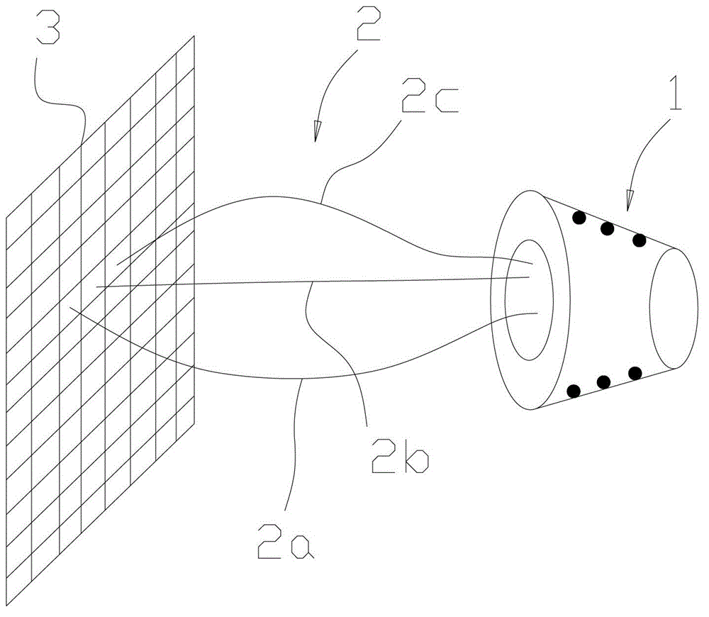
[0029] Such as figure 2 As shown, this embodiment describes a fiber optic display device, including:

[0030] The optical fiber display light source structure 1 described in Embodiment 1;

[0031] The optical fiber 2 has a light-entrance end and a light-exit end, the light-entry end of the optical fiber 2 is connected to the fiber connection area 103a of the optical fiber display light source structure 1, and the axial direction of the light-entrance end is perpendicular to the fiber connection surface 103 ;

[0032] The display panel 3 is connected with the light output end of the optical fiber 2 and is used for displaying patterns.

[0033] In this embodiment, the light-incoming end and the light-outgoing end of the optical fiber 2 have hemispherical light-incoming surfaces and light-outgoing surfaces, respectively.

[0034] In this embodiment, the display panel 3 includes a color filter layer. In this embodiment, the color filter layer adopts the color filter layer use...


PUM


Abstract

The invention discloses an optical fiber display light source structure of a hollow conical platform structure. One of the upper bottom surface, the side surface and the lower bottom surface of the hollow conical platform structure is formed by a light source, a reflection cover and an optical fiber connecting surface, wherein a light outgoing surface of the light source is arranged towards the optical fiber connecting surface; a reflection surface of the reflection cover is located at the inner side of the side surface; and the optical fiber connecting surface is provided with an optical fiber connecting region which corresponds to the position of the light source and is the same as the light source in size. The invention further discloses an optical fiber display device comprising the optical fiber display light source structure, an optical fiber and a display panel, wherein the optical fiber is provided with a light incoming end and a light outgoing end; the light incoming end of the optical fiber is connected with the optical fiber connecting region of the optical fiber display light source structure; the axial direction of the light incoming end is vertical to the optical fiber connecting surface; and the display panel is connected with the light outgoing end of the optical fiber and is used for displaying an image. The optical fiber display light source structure can more effectively utilize the light source to further clearly display the image.

Description

technical field [0001] The invention relates to the field of display technology, in particular to an optical fiber display light source structure and an optical fiber display device. Background technique [0002] A fiber optic display device in the prior art includes a display panel, several optical fibers fixed on the display panel, and a light source located on one side of the light incident surface of the several optical fibers. Due to the long distance between the light source and the incident surface of the optical fiber, most of the light emitted by the light source cannot be incident vertically on the cross-section of the optical fiber, thus failing to meet the high brightness and high definition requirements of today's image display. degree requirements. Furthermore, the light source used in the prior art is an incandescent bulb, so when the display screen is made large enough, the display effect will also be affected. In addition, in terms of realizing color, the ...

Claims


Application Information

Patent Timeline
Patent Type & Authority Applications(China)
IPC IPC(8): G09F9/305G02B6/06
CPCF21V9/08F21V7/0058G02B6/0005G02B6/0006G09F9/305
Inventor 王英涛柳在健姚继开
Owner BOE TECH GRP CO LTD
Learn More