Protection switching method and system and optical network node

A technology of optical network node and protection switching, which is applied in the direction of transmission system, electromagnetic wave transmission system, transmission monitoring/testing/fault measurement system, etc. It can solve the problems of the total time-consuming protection switching process, and save the total time-consuming protection switching, Savings are noticeable

Active Publication Date: 2013-01-09
ZTE CORP
View PDF5 Cites 20 Cited by
  • Summary
  • Abstract
  • Description
  • Claims
  • Application Information

AI Technical Summary

Problems solved by technology

[0005] Embodiments of the present invention provide a protection switching method, system, and optical network node, which are used to solve the problem that the protection swi...

Method used


Image

  • Protection switching method and system and optical network node
  • Protection switching method and system and optical network node
  • Protection switching method and system and optical network node

Examples


Embodiment 1

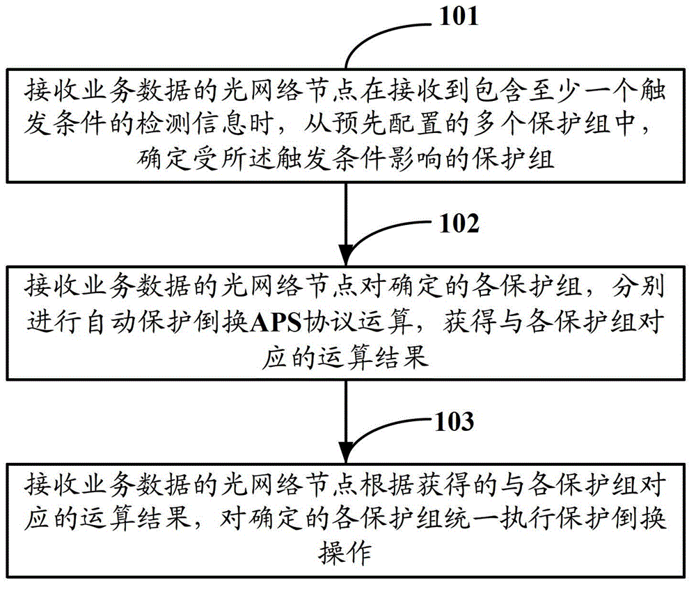
[0046] Such as figure 1 As shown, it is a schematic flow chart of the protection switching method in Embodiment 1 of the present invention, and the method includes the following steps:

[0047] Step 101: When an optical network node receiving service data receives detection information containing at least one trigger condition, it determines a protection group affected by the trigger condition from a plurality of pre-configured protection groups.

[0048] Described trigger condition refers to in the optical network, can be used for the trigger condition of APS protocol operation, according to whether trigger condition is a command configuration class, it is divided into A type trigger condition and B type trigger condition two types, specifically as follows:

[0049] Type A trigger conditions include: WsfSta, WsdSta, PsfSta, PsdSta and ApsSignal;

[0050] Type B trigger conditions include: ExtractCommand, UpdatedCfg, and WtrSta.

[0051] Among them, WsfSta indicates the fail...

Embodiment 2

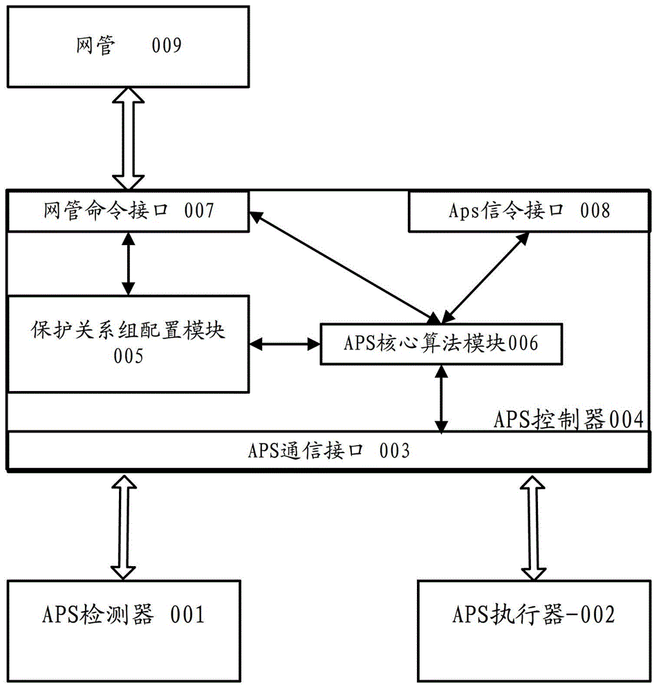
[0079] Such as image 3 As shown, it is a schematic diagram of the functional structure of the network protection system in Embodiment 2 of the present invention, including: APS detector 001, APS actuator 002, APS communication interface 003, APS controller 004, network management command interface 007, APS signaling interface 008 and Network management 009, wherein APS controller 004 includes: protection group configuration module 005, APS core algorithm module 006; wherein:

[0080] The APS detector 001 is used to detect the status of the working / protection link in real time. When the link status changes, the detection information including the specific link status is transmitted to the APS controller 002 through the APS communication interface 003; when supporting APS signaling In the delivered system, the working link is also responsible for the detection, extraction and insertion of changes in the local received remote APS signaling.

[0081] The APS controller 004 is ...

Embodiment 3

[0091] Based on the protection switching method in Embodiment 1 and the network protection system in Embodiment 2 above, Embodiment 3 of the present invention provides a protection switching method, specifically as follows:

[0092] Step 1: Pre-construct a two-level dynamic binding relationship grid.

[0093] The purpose of building a two-level dynamic binding relationship grid is to establish the relationship between fault detection ports and protection groups, and to establish the relationship between protection groups with the same APS protocol status. In this step, the Protection groups belong to the same group node. In order to facilitate operations on protection groups (such as searching, inserting, deleting, modifying, etc.), each protection group is organized together in the data structure form of a doubly linked list, and the nodes of each group are organized together using a doubly linked list to form a grid shape structure. The specific construction process is as ...


PUM


Abstract

The invention discloses a protection switching method and system and an optical network node. The protection switching method comprises the steps of: when receiving detection information including at least one trigger condition, determining protection groups influenced by the trigger condition from a plurality of pre-configured protection groups, respectively carrying out automatic protection switching (APS) protocol operation on the determined protection groups to obtain operation results corresponding to the protection groups, and uniformly executing protection switching operation on the determined protection groups according to the operation results. In the scheme provided by the invention, because the APS protocol operation is carried out on the determined protection groups influenced by the trigger condition centrally, the protection switching operation is uniformly executed on the determined protection group, and a once protection switching mechanism is triggered by only calling a once APS protocol processing program, therefore, compared with the mode of serially executing the protection operation on the protection groups, the protection switching method has the advantage of greatly saving total time consumption of protection switching.

Description

technical field [0001] The invention relates to the technical field of optical network protection, in particular to a protection switching method, system and optical network node. Background technique [0002] With the rapid development of optical network applications, once the optical network carrying large-capacity service information fails, the loss will be huge. However, in the optical network, faults such as fiber breakage, optical network node failure, and signal degradation are unavoidable. Therefore, relevant measures need to be taken in the optical network to achieve network survivability of the optical network. [0003] The so-called network survivability refers to the ability of the network to maintain a tolerable service level in a very short period of time without human intervention when a network device fails. In an optical network, the way to realize network survivability includes network protection and network restoration. Among them, network protection ref...

Claims


Application Information

Patent Timeline
IPC IPC(8): H04B10/032H04B10/07
Inventor 郭晓波郭艳刘晶
Owner ZTE CORP
Why Eureka
Try Eureka