Transmission switching method and system under base station straight-through architecture

A switching system and base station technology, applied in the field of communication, can solve the problems of increasing the burden of the core network, frequent switching, etc., and achieve the effect of reducing the transmission burden

Active Publication Date: 2013-01-09
CHINA UNITED NETWORK COMM GRP CO LTD
View PDF5 Cites 2 Cited by
  • Summary
  • Abstract
  • Description
  • Claims
  • Application Information

AI Technical Summary

Problems solved by technology

[0005] Due to the mobility of the terminal, the handover of the terminal between base stations is very frequent, and all the messages sent by the terminal during the handover operation of the base station need to pass through the core network, which greatly increases the burden on the core network

Method used


Image

  • Transmission switching method and system under base station straight-through architecture
  • Transmission switching method and system under base station straight-through architecture
  • Transmission switching method and system under base station straight-through architecture

Examples


Embodiment 1

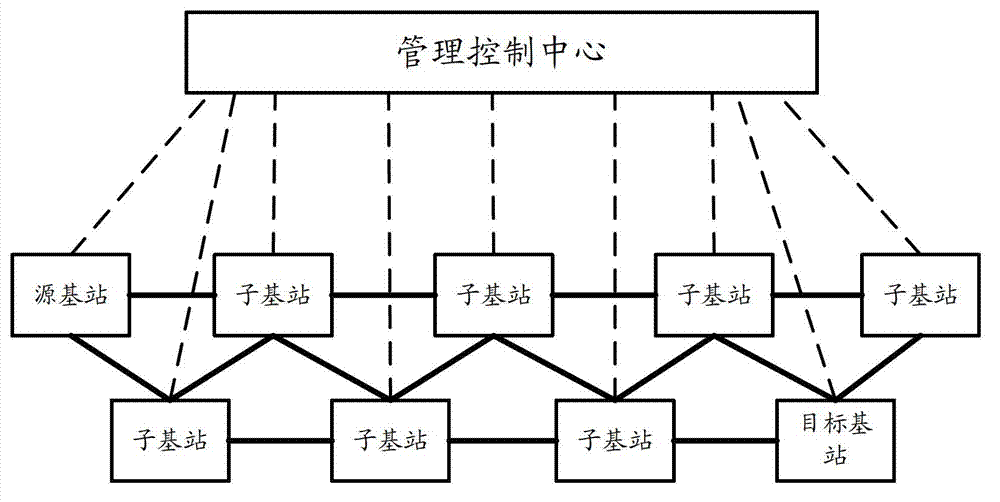
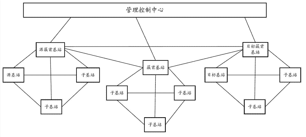
[0026] This embodiment provides a method for transmission switching in a base station direct architecture. The method of this embodiment is particularly suitable for Figure 2A~2E The network architecture shown. Such as Figure 2A As shown, the access network includes a management control center and multiple base stations, and each base station is connected to the management control center. The management control center receives the service request of each base station, and sends connection signaling according to the service request, so that a direct data channel is established between the base stations, so that data or signaling can be directly transmitted between the base stations. Such as Figure 2B~2E As shown, all are different forms of clustering network architecture. Such as Figure 2B with 2C As shown, the access network includes a management control center, cluster head base stations and sub base stations. Multiple cluster head base stations are connected to th...

Embodiment 2

[0081] This embodiment further describes the handover process between the handover source base station and the handover destination base station in step 401, and other steps are consistent with the above-mentioned embodiments, and will not be repeated here. In this embodiment, the operation of the handover target base station is specifically described.

[0082] Specifically, the operation of the handover destination base station may be as follows:

[0083] Step A, when the handover target base station receives the handover request message sent by the handover source base station through the data direct channel, according to the handover request message, reserve air interface resources for the user to be accessed and allocate a cell radio network temporary identifier (Cell Radio Network Temporary Identifier, C-RNTI), and set the user's access priority to high.

[0084] The handover request message may include the identification number or telephone number of the user to be acce...

Embodiment 3

[0089] This embodiment provides a transmission switching system under the base station direct architecture, which is used to implement the transmission switching method under the base station direct architecture of the first embodiment.

[0090] Such as Figure 5 As shown, it is a schematic structural diagram of a transmission switching system under the base station direct architecture according to this embodiment. The transmission handover system under the base station direct architecture includes a handover source base station 501 and a handover destination base station 503 .

[0091]Wherein, the handover source base station 501 is respectively connected with the handover destination base station 503 and the receiving user 601, and is used for identifying the current data packet to be sent when receiving a message indicating that the handover between the handover source base station 501 and the handover destination base station 503 is successful, And sent to the receiving u...


PUM


Abstract

The invention provides a transmission switching method and system under a base station straight-through architecture. The method comprises the following steps of: marking a current data packet to be sent when a switching source base station receives a message indicating that the switching between the switching source base station and a switching target base station is successful, sending the message to a receiving user, and sending follow-up data packets to be sent in a cache to the switching target base station through a data straight-through channel after marking the follow-up data packets; caching the data packets received by the switching target base station, and sequencing all the data packets when the marked data packets are identified; and notifying the switching source base station of re-transmitting the data packets corresponding to missed serial numbers by the switching target base station through the data straight-through channel according to the sequencing result. According to the transmission switching method and system under the base station straight-through architecture, provided by the embodiment, data transmission during the switching of the base stations can be completed through the data straight-through channel, and the pressure of a core network can be reduced.

Description

technical field [0001] The present invention relates to communication technology, in particular to a transmission switching method and system under a base station direct architecture. Background technique [0002] In the 3G system, base station networking adopts a hierarchical deployment mode. Multiple NodeBs (Node Bs) can be connected to a unified RNC (Radio Network Controller, wireless controller), and connected to the core network through the RNC. [0003] Such as figure 1 As shown, when the source NodeB 101 covering the source user needs to send service data to the target NodeB 104 covering the target user, the service data is first sent to the source RNC 102 through the source NodeB 101, and the source RNC 102 transmits the service data to the core network 103, and then send it to the target RNC 105 to which the target NodeB 104 belongs after gathering through the core network 103, and then send the service data to the target NodeB 104 through the target RNC 105 to wh...

Claims


Application Information

Patent Timeline
Patent Type & Authority Applications(China)
IPC IPC(8): H04W36/00H04W36/08
Inventor 孙雷吕召彪王健全
Owner CHINA UNITED NETWORK COMM GRP CO LTD
Why Eureka
Try Eureka