Boundary layer control and mainstream perturbation coordinated integrated enhanced heat transfer method and system
A technology to strengthen heat exchange and boundary layer, applied in the field of dehumidification and drying, it can solve the problem that the mainstream short flow cannot be fully heated, cooled, and hinder the transfer of cold and heat.
- Summary
- Abstract
- Description
- Claims
- Application Information
AI Technical Summary
Problems solved by technology
Method used
Image
Examples
Embodiment 1
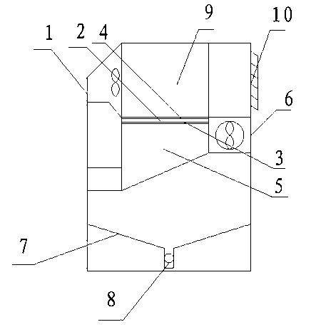
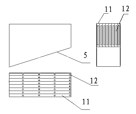
[0034] Boundary layer control combined with mainstream disturbance integrated enhanced heat transfer system, such as figure 1 , 2 As shown in . Below the cold end surface 3, the right side of the fin group 5 at the cooling end is connected to the air inlet 6, and a sump 7 is arranged under the fin group 5 at the cooling end, and a drain port 8 is opened under the sump 7, and the fin group 9 at the heating end is connected to Above the hot end surface 4, the right end of the heating end fin group 9 is connected to the exhaust port 10. The cooling end fin group 5 is composed of a plurality of cooling end fins 11 longitudinally arranged in front and back. The sheet group 9 is composed of a plurality of fins 14 at the heating end longitudinally arranged front and back, and the fins 11 at the cooling end are trapezoidal in longitudinal section and rectangular in cross section. A plurality of boundary layer flow control devices 12 are longitudinally arranged on the cooling end fin...
Embodiment 2
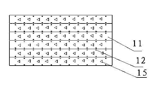
[0036] Boundary layer control combined with mainstream disturbance integrated enhanced heat transfer system, such as figure 1 , 3 As shown in . Below the cold end surface 3, the right side of the fin group 5 at the cooling end is connected to the air inlet 6, and a sump 7 is arranged under the fin group 5 at the cooling end, and a drain port 8 is opened under the sump 7, and the fin group 9 at the heating end is connected to Above the hot end surface 4, the right end of the heating end fin group 9 is connected to the exhaust port 10. The cooling end fin group 5 is composed of a plurality of cooling end fins 11 longitudinally arranged in front and back. The sheet group 9 is composed of a plurality of fins 14 at the heating end longitudinally arranged front and back, and the fins 11 at the cooling end are trapezoidal in longitudinal section and rectangular in cross section. A plurality of boundary layer flow control devices 12 are longitudinally arranged on the cooling end fin...
Embodiment 3
[0038] Boundary layer control combined with mainstream disturbance integrated enhanced heat transfer system, such as figure 1 , 4 As shown in . Below the cold end surface 3, the right side of the fin group 5 at the cooling end is connected to the air inlet 6, and a sump 7 is arranged under the fin group 5 at the cooling end, and a drain port 8 is opened under the sump 7, and the fin group 9 at the heating end is connected to Above the hot end surface 4, the right end of the heating end fin group 9 is connected to the exhaust port 10. The cooling end fin group 5 is composed of a plurality of cooling end fins 11 longitudinally arranged in front and back. The sheet group 9 is composed of a plurality of heating end fins 14 longitudinally arranged front and back, the longitudinal section of the cooling end fins 11 is trapezoidal, the cross section is W-shaped, and the surface of the cooling end fins 11 is provided with a screen 13 . A plurality of boundary layer flow control devi...
PUM
 Abstract
Description
Claims
Application Information
 - R&D
- Intellectual Property
- Life Sciences
- Materials
- Tech Scout
- Unparalleled Data Quality
- Higher Quality Content
- 60% Fewer Hallucinations
Browse by: Latest US Patents, China's latest patents, Technical Efficacy Thesaurus, Application Domain, Technology Topic, Popular Technical Reports.
© 2025 PatSnap. All rights reserved.Legal|Privacy policy|Modern Slavery Act Transparency Statement|Sitemap|About US| Contact US: help@patsnap.com


