
Electrode and machining method for electrolytic grooving of blisks

An integral blisk and groove machining technology, applied in electric machining equipment, electrochemical machining equipment, machining electrodes, etc., can solve the problems of uneven machining allowance, inability to achieve precision electrolytic machining without allowance, disadvantageous blade profile machining, etc. To achieve the effect of improving the grooving processing efficiency, good economic benefits, and uniform allowance

Active Publication Date: 2013-01-16
SHENYANG LIMING AERO-ENGINE GROUP CORPORATION
View PDF5 Cites 17 Cited by
  • Summary
  • Abstract
  • Description
  • Claims
  • Application Information

AI Technical Summary

Problems solved by technology

[0003] At present, the electrolytic grooving of the blisk is carried out by nesting. The nesting process uses an electrode that is similar to the cross-sectional shape of the blade. When using nesting processing, while the electrode is feeding in a straight line, the electrode also rotates according to the torsion angle of the blade to process the flow channel of the blade. The disadvantage of this method is that the cross-sectional shape of the processed blade is the same. Each section of the upper blade is different, and the machining allowance left for the follow-up process of airfoil finishing is uneven, which is very unfavorable to the subsequent airfoil processing, and it is impossible to realize precision electrolytic machining without allowance

Method used


Image

  • Electrode and machining method for electrolytic grooving of blisks
  • Electrode and machining method for electrolytic grooving of blisks
  • Electrode and machining method for electrolytic grooving of blisks

Examples


Embodiment 1

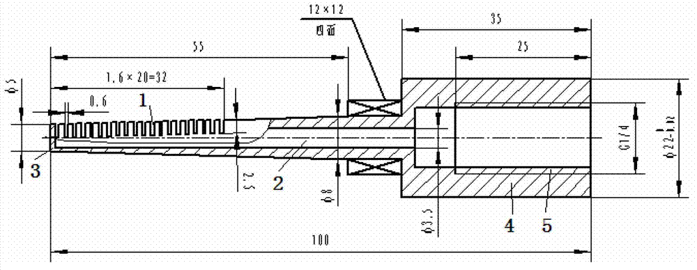
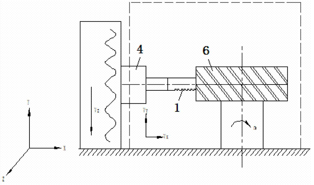
[0024] An electrode for electrolytic grooving of an integral blisk, characterized in that: the electrode for electrolytic grooving of an integral blisk is a hollow finger-like structure as a whole, and the hollow structure inside the electrode is mainly used as a channel for an electrolyte. There is a narrow groove 1 with a width of 0.6mm at intervals of 1mm along the circumferential direction 1 / 3-1 / 2 of the section of the fingertip ≤ 1 / 2 of the full length, so that the electrolyte can communicate through the narrow groove To the processing area; the inside of the electrode for electrolytic slotting of the integral blisk is provided with an electrolyte delivery pipeline 2; the finger end of the electrolyte delivery pipeline 2 near the processing section is provided with a plugging structure 3, so that the electrolysis The liquid delivery pipeline 2 is a blind hole structure, and the electrolyte can only flow out from the narrow groove 1 .

[0025] Under the action of the elect...


PUM

PropertyMeasurementUnit
lengthaaaaaaaaaa
lengthaaaaaaaaaa
lengthaaaaaaaaaa

Abstract

An electrode for electrolytic grooving of blisks is integrally of a hollow finger-shaped structure. An electrolyte channel is arranged inside the electrode, narrow grooves (1) with the widths of 0.6mm are circumferentially arranged at intervals of 1mm and are positioned at locations distanced from the upper edge of an outer profile close to a finger end of the electrode by 1 / 3-1 / 2, an electrolyte delivery pipeline (2) is disposed inside the electrode, a plugging structure (3) is arranged at the finger end so that the electrolyte delivery pipeline (2) is of a blind hole structure, and electrolyte only can flow out from the narrow grooves (1). A machining method for electrolytic grooving of the blisks includes that the electrode for electrolytic grooving of the blisks is used as a special tool, and an anode of a workpiece is dissolved in the electrolyte under the action of an electric field, so that the purpose of performing dimension machining for the workpiece is achieved; and the pressure of the electrolyte ranges from 4MPa to 6MPa, and the allowance reserved on a profile of a blisk body is 3.5mm. The electrode and the machining method have the advantages that the allowance reserved during electrolytic machining is uniform, high precision of repetition can be realized easily, a good flow field is obtained during electrolytic machining, and machining efficiency is high.

Description

technical field [0001] The invention relates to the technical field of electrolytic machining of mechanical structural parts, and in particular provides an electrode for electrolytic slotting of an integral blisk. Background technique [0002] In the newly developed fourth-generation aero-engine, in order to improve the thrust-to-weight ratio of the engine, a new structure-integral blisk is adopted. The overall blisk requires high machining accuracy and is difficult to process. The electrolytic machining of the blisk is a high-efficiency, high-quality, and low-cost processing method. The electrolytic machining of the blisk is divided into slotting processing (or runner processing) and airfoil surface processing. The requirements for electrolytic grooving are: the processing efficiency should be high, and the allowance for the electrolytic precision machining of the airfoil profile should be uniform, so that the airfoil finishing process can meet the drawing requirements. F...

Claims


Application Information

Patent Timeline
Patent Type & Authority Applications(China)
IPC IPC(8): B23H3/00B23H3/04
Inventor 王德新朱海南于冰盛文娟
Owner SHENYANG LIMING AERO-ENGINE GROUP CORPORATION
Learn More