Shell-and-tube heat exchanger provided with blade type clapboards

A shell-and-tube heat exchanger and baffle technology, applied in the direction of heat exchanger type, heat exchanger shell, indirect heat exchanger, etc., can solve the problems of difficult processing, high manufacturing cost, complex structure, etc., to avoid flow Dead space, easy to manufacture and install, improved environmental effect

Inactive Publication Date: 2013-01-16
山东双涵石化装备有限公司 +1
View PDF3 Cites 3 Cited by
  • Summary
  • Abstract
  • Description
  • Claims
  • Application Information

AI Technical Summary

Problems solved by technology

However, the full circular orifice plate is suitable for medium and low viscosity fluids and the occasions where the Reynolds number is not large, and the structure is complicated, the processing is difficult, and the manufacturing cost is high

Method used


Image

  • Shell-and-tube heat exchanger provided with blade type clapboards
  • Shell-and-tube heat exchanger provided with blade type clapboards
  • Shell-and-tube heat exchanger provided with blade type clapboards

Examples


Embodiment 1

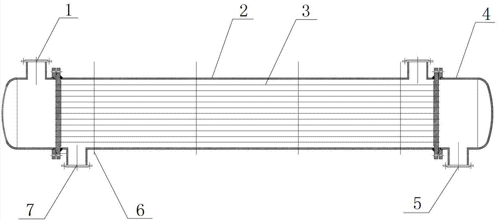
[0024] Such as figure 1 As shown in the figure, the vane-type baffle shell-and-tube heat exchanger includes a shell 2 and heat exchange tubes 3. A guide tube 7 is provided on both sides of the shell 2, and a cover 4 is provided at both ends of the shell 2. The cover 4 is respectively provided with a shell-side inlet 1 and a shell-side outlet 5 , and fan-blade partitions 6 are installed between the heat exchange tubes 3 .

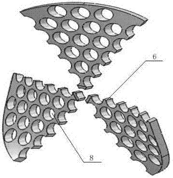
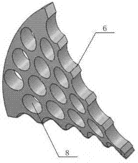
[0025] Such as Figure 2-5 As shown, a plurality of through holes 8 are provided on the blade-shaped partition 6 , and the heat exchange tubes 3 pass through the through holes 8 and are fixed in the casing 2 .

[0026] The fluid enters the heat exchanger through the shell-side inlet, and passes through the guide tubes at both ends of the shell, so that the shell-side fluid sweeps the tube bundle longitudinally on the one hand, and changes the flow direction repeatedly on the other hand, thereby enhancing heat transfer.

Embodiment 2

[0028] On the basis of Embodiment 1, the outer diameter of the fan-shaped partition 6 is the same as the inner diameter of the shell 2 , and there is a gap between the through hole 8 and the heat exchange tube 3 . Let the fluid pass through enough gaps, reduce the flow dead zone, reduce the shell side pressure, and inhibit the accumulation and precipitation of fluid dirt.

Embodiment 3

[0030] On the basis of Examples 1 and 2, such as figure 2 , Figure 4 , Figure 5 As shown, the fan-shaped partition 6 is composed of 3 fan-shaped partitions of equal size, the central angle of the fan-shaped partition is 60 degrees, and the 3 fan-shaped partitions of the fan-blade partition 6 form the same angle with the vertical direction, 3 The angle between the first fan-shaped partition and the vertical direction is 10 degrees, and the blade-shaped partitions 6 are placed alternately. The latter partition rotates clockwise at the same angle relative to the previous partition, and the rotation angle of the fan-shaped partitions 6 is 60 degrees. .

[0031] The fan-blade partitions are arranged alternately, and the difference between two adjacent partitions is the same angle, that is, the latter partition rotates clockwise around the center by the same angle relative to the previous partition, and so on. The staggered position of each fan-shaped partition is used to orga...


PUM


Abstract

The invention discloses a tubular heat exchanger with high heat transfer coefficient and low pressure loss, in particular relating to a shell-and-tube heat exchanger provided with blade type clapboards. The shell-and-tube heat exchanger comprises a shell (2) and heat exchange pipes (3); the shell-and-tube heat exchanger is characterized in that the two sides of the shell (2) are provided with guide cylinders (7), the two ends of the shell (2) are provided with sealing covers (4), a shell pass inlet (1) and a shell pass outlet (5) are respectively arranged on the sealing covers (4) of the two ends; every blade type clapboard (6) is arranged between the heat exchange pipes (3); a quantity of through holes (8) are arranged in the blade type clapboards (6); the heat exchange pipes (3) pass through the through holes (8) and are fixed in the shell (2). The outer diameters of the blade type clapboards (6) are same as the inner diameter of the shell (2); and gaps are formed among the through holes (8) and the heat exchange pipes (3). With the adoption of the shell-and-tube heat exchanger, enough strength disturbance is guaranteed, at the same time, the pressure loss of a shell pass fluid is effectively reduced, the heat transfer temperature difference is reduced, the total heat transfer coefficient is improved, the fluid outside the pipe is low in flowing resistance and good in heat exchange effect, and the shell-and-tube heat exchanger is convenient to produce and mount and long in service life.

Description

technical field [0001] The invention relates to a tube heat exchanger with high heat transfer coefficient and low pressure drop, in particular to a shell-and-tube heat exchanger with a vane type diaphragm. Background technique [0002] The traditional shell-and-tube heat exchanger has the advantages of simple structure, high reliability, wide adaptable pressure range, large selection range, low cost, mature design, manufacture and practical technology, especially when dealing with high flow rates, temperatures and pressures. In the case of parameters, the shell and tube heat exchanger highlights its advantages. Therefore, shell and tube heat exchangers are widely used in petroleum, chemical, energy, power, metallurgy and other fields. However, traditional heat exchangers generally use smooth tubes or special-shaped tubes as heat transfer elements; baffles or baffle rods support the tube bundles and also have the function of guiding flow. When the shell side fluid flows, a ...

Claims


Application Information

Patent Timeline
Patent Type & Authority Applications(China)
IPC IPC(8): F28D7/00F28F9/22
Inventor 张春霞张希忠马虎根高慧童娇妹姜圣列
Owner 山东双涵石化装备有限公司
Why Eureka
Try Eureka