Voltage detection device, system and method

A voltage detection method and voltage detection technology, applied in the field of electronics, can solve problems such as low reliability, normal chip business impact, and system failure to detect alarms, and achieve the effect of improving system reliability

Inactive Publication Date: 2013-01-16
HUAWEI TECH CO LTD
View PDF4 Cites 13 Cited by
  • Summary
  • Abstract
  • Description
  • Claims
  • Application Information

AI Technical Summary

Problems solved by technology

However, factors such as the internal junction temperature of the chip or the manufacturing process will cause the actual VID of the chip to change, and accordingly, the acceptable operating voltage range of the chip will also change.
Comparing the actual voltage of the chip with the acceptable operating voltage range specified by the preset VID cannot truly reflect the overvoltage or undervoltage condition of the chip, which may cause the actual voltage of the chip to exceed the acceptable operating voltage range of the chip. , the system cannot detect the alarm, which affects the normal operation of the chip and lowers the reliability

Method used


Image

  • Voltage detection device, system and method
  • Voltage detection device, system and method
  • Voltage detection device, system and method

Examples


Embodiment 1

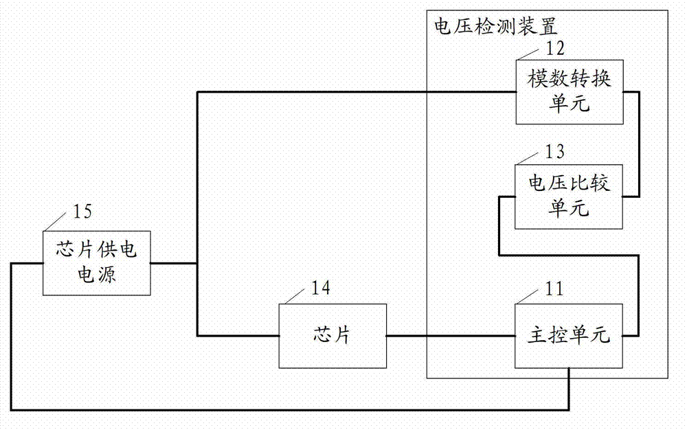
[0045] An embodiment of the present invention provides a voltage detection device, such as figure 1 As shown, it includes a main control unit 11 , an analog-to-digital conversion unit 12 and a voltage comparison unit 13 . in:

[0046] The main control unit 11 is connected with the chip 14, and is used to receive the real-time VID of the chip 14, convert the real-time VID of the chip 14 into the acceptable working voltage range of the chip 14 specified by the real-time VID, and accept the working voltage range of the chip 14 specified by the real-time VID. The voltage range is supplied to the voltage comparison unit 13 .

[0047] The analog-to-digital conversion unit 12 is connected to the chip power supply 15, and is used to receive the actual voltage analog signal provided by the chip power supply 15, convert the actual voltage analog signal into an actual voltage value, and provide the actual voltage value to the voltage A comparison unit 13 ; wherein, the chip power supply ...

Embodiment 2

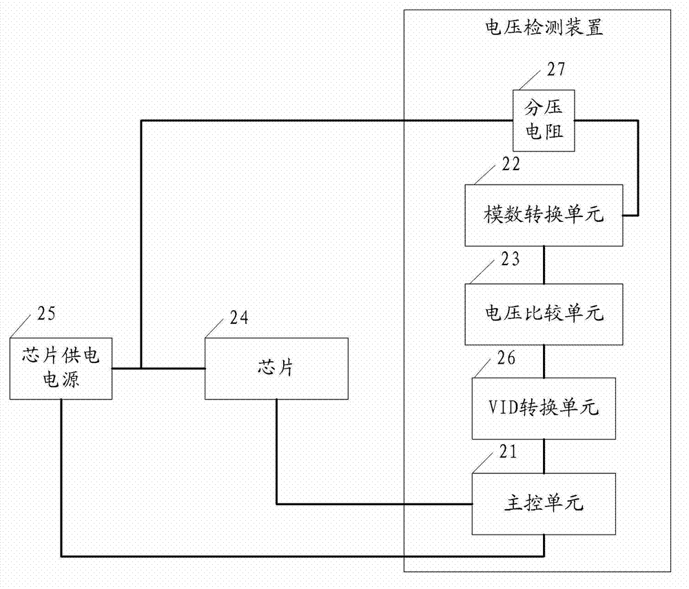
[0058] An embodiment of the present invention provides a voltage detection device, such as figure 2 As shown, the voltage detection device includes a main control unit 21 , an analog-to-digital conversion unit 22 , a voltage comparison unit 23 and a VID conversion unit 26 .

[0059] The main control unit 21 is connected to the chip 24 for receiving the real-time VID of the chip 24 and providing the real-time VID of the chip 24 to the VID converting unit 26 .

[0060] The analog-to-digital conversion unit 22 is connected to the chip power supply 25, and is used to receive the actual voltage analog signal provided by the chip power supply 25, convert the actual voltage analog signal into an actual voltage value, and provide the actual voltage value to the voltage A comparison unit 23 ; wherein, the chip power supply 25 is used to supply power to the chip 24 .

[0061] The VID conversion unit 26 is used to receive the real-time VID sent by the main control unit 21, convert the ...

Embodiment 3

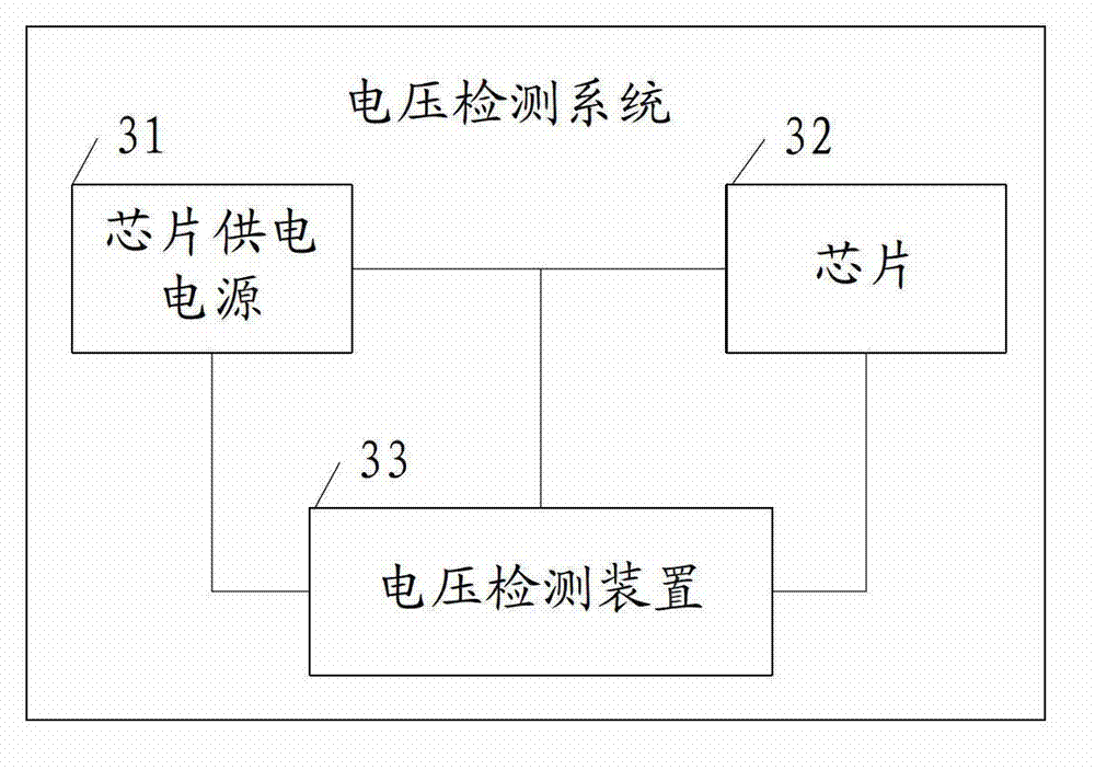
[0071] An embodiment of the present invention provides a voltage detection system, such as image 3 As shown, it includes: a chip 31 , a chip power supply 32 and the aforementioned voltage detection device 33 .

[0072] The chip power supply 32 is respectively connected to the chip 31 and the voltage detection device 33 to provide voltage for the chip 31 and the voltage detection device 33 .

[0073] The chip 31 is connected to the voltage detection device 33 and sends the real-time VID of the chip 31 to the voltage detection device 33 .

[0074] Among them, the chip power supply 32 provides actual voltages for the chip 31 and the voltage detection device 33 respectively, the chip 31 adjusts the real-time VID information according to its internal junction temperature and manufacturing process, and the voltage detection device 33 obtains the real-time VID information from the chip 31. In the voltage detection device 33, the actual voltage value is compared with the acceptable ...


PUM


Abstract

The invention discloses a voltage detection device, a system and a method, relating to the field of electronics and capable of dynamically carrying out overvoltage or undervoltage detection on the voltage of a chip power supply in real time so as to improve the system reliability. The voltage detection device comprises a master control unit, an analog-to-digital conversion unit and a voltage comparison unit, wherein the master control unit is connected with a chip and is used for receiving the real-time VID (voltage identity) of the chip and converting the real-time VID in a chip acceptable working voltage range required by the real-time VID and then providing the converted real-time VID to the voltage comparison unit, the analog-to-digital conversion unit is connected with the chip power supply and is used for receiving a real voltage analog signal provided by the chip power supply, converting the real voltage analog signal into a real voltage value and then providing the converted real voltage value to the voltage comparison unit, the voltage comparison unit is connected with the master control unit and the analog-to-digital conversion unit respectively and is used for determining whether the real voltage value is beyond the chip acceptable working voltage range required by the real-time VID. The voltage detection device, the system and the method are used for the overvoltage/undervoltage detection of an automatic voltage adjustment power supply.

Description

technical field [0001] The invention relates to the field of electronics, in particular to a voltage detection device, system and method. Background technique [0002] In the design of electronic equipment, multiple chips powered by the same power supply can be divided into fast processing (English full name is Fast process), normal processing (English full name is Normal process) and slow processing (English full name) due to different processing performance and business load. The full name is Slow process) three processing states. The speed and overall power consumption of different chips are different, so the voltage requirements of different chips must be met when performing single-board thermal design and power supply design. Therefore, the working voltage of the Fast process chip can be slightly lower to ensure stable and normal operation, and the working voltage of the Slow process chip can be slightly higher to ensure stable and normal operation. In order to preven...

Claims


Application Information

Patent Timeline
Patent Type & Authority Applications(China)
IPC IPC(8): G01R19/165
Inventor 吕杰
Owner HUAWEI TECH CO LTD
Why Eureka
Try Eureka