Lower template of punching machine

A stamping machine tool and template technology, which is applied in the direction of metal processing equipment, forming tools, manufacturing tools, etc., can solve the problems affecting production efficiency and continuous type, and achieve the effect of improving production efficiency, increasing continuous type, and convenient removal

Inactive Publication Date: 2013-01-23
SUZHOU TANGFENG METAL PROD
View PDF0 Cites 0 Cited by
  • Summary
  • Abstract
  • Description
  • Claims
  • Application Information

AI Technical Summary

Problems solved by technology

[0003] The lower template of the existing stamping machine tool is usually set in the workbench of the stamping machine tool. After the stamping is completed, the stamped parts are still embedded in the stamping area, and then manually removed by the operator. This method obviously affects the continuous production. Affected production efficiency

Method used


Image

  • Lower template of punching machine
  • Lower template of punching machine

Examples


Embodiment Construction

[0012] The present invention is described below in conjunction with accompanying drawing.

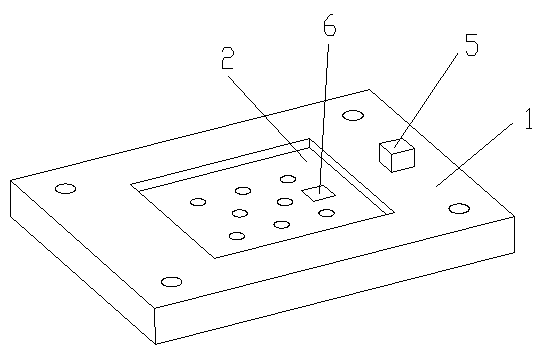
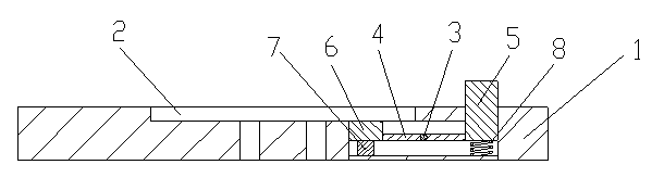
[0013] as attached figure 1 , 2 The shown lower formwork of a stamping machine tool according to the present invention includes a lower formwork body 1 and a stamping area 2; the center of the upper surface of the lower formwork body 1 is provided with a stamping area 2; stamping parts are placed in the stamping area 2 ; The inside of the lower template body 1 is provided with a lever mechanism for jacking up the stamping parts; the lever mechanism includes a rotating shaft 3, a support rod 4, a press block 5, a top block 6, a support seat 7 and a spring 8; The shaft 3 is arranged below the stamping area; the support rod 4 is arranged in the lower template body 1 through the rotating shaft 3; the press block 5 and the top block 6 are respectively arranged at both ends of the support rod 4; The lower part is provided with a spring 8; the upper surface of the press block 5 is higher tha...


PUM


Abstract

The invention discloses a lower template of a punching machine, belonging to the technical field of punching components. The lower template comprises a lower template body and a punching region; the punching region is arranged at the center of the upper surface of the lower template body; a punching part is arranged in the punching region; and a lever mechanism capable of jacking the punching part is arranged in the lower template body. According to the lower template of the punching machine provided by the invention, owing to the lever mechanism capable of jacking the punching part, the punching part is taken out conveniently, the working intensity of an operator is reduced, and the production continuity is increased, thus the production efficiency is improved.

Description

technical field [0001] The invention relates to a lower template of a stamping machine tool, in particular to a lower template of a stamping machine tool which is convenient for taking out stamping parts, and belongs to the technical field of stamping machine tool components. Background technique [0002] Stamping machine tools are referred to as stamping machines, also known as presses, which are equipment used for pressure processing of materials. Its working principle is generally to drive the opening and closing of the upper mold and the lower mold by the machine tool under the action of stamping power, and then cut, punch, stretch and other raw materials between them to form stamping parts. According to the working principle of the press, it can be divided into mechanical press and hydraulic press. The mechanical press completes the stamping process through the motor-driven slider movement; the hydraulic press uses the hydraulic principle to drive the hydraulic steel t...

Claims


Application Information

Patent Timeline
Patent Type & Authority Applications(China)
IPC IPC(8): B21D37/10B21D45/02
Inventor 唐剑峰
Owner SUZHOU TANGFENG METAL PROD
Why Eureka
Try Eureka