
Clamping type mechanical antitheft lock

A technology of mechanical anti-theft locks and lock bodies, which is applied in construction locks, cylinder pin locks, and locks with rotating keys, etc. It can solve the problems of reduced mechanical strength, complex structure, and increased number of keys, etc., and achieves simple operation, The effect of low cost and easy processing and manufacturing

Active Publication Date: 2013-01-23
如东县岔河污水处理有限公司
View PDF4 Cites 14 Cited by
  • Summary
  • Abstract
  • Description
  • Claims
  • Application Information

AI Technical Summary

Problems solved by technology

[0003] In order to improve the protection level of anti-theft locks, most designers try their best to complicate the internal structure of the lock cylinder, strive to be novel and unique, and increase the number of keys. The disadvantages are that the accuracy requirements and manufacturing difficulty are increased, and the cost is also increased. Doing so may lead to a reduction in mechanical strength, and special high-quality materials are required to improve mechanical strength to prevent damage
There are also locks with strong anti-opening ability, but the unlocking operation process is relatively cumbersome.

Method used


Image

  • Clamping type mechanical antitheft lock
  • Clamping type mechanical antitheft lock
  • Clamping type mechanical antitheft lock

Examples


Embodiment Construction

[0020] The following examples are used to illustrate the present invention, but are not intended to limit the scope of the present invention.

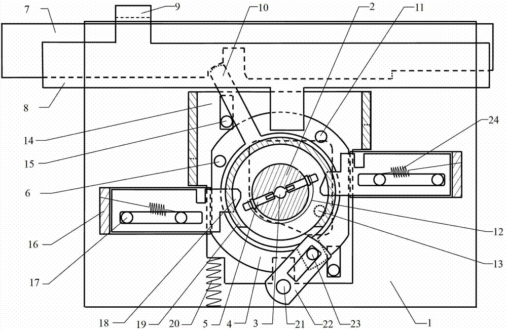
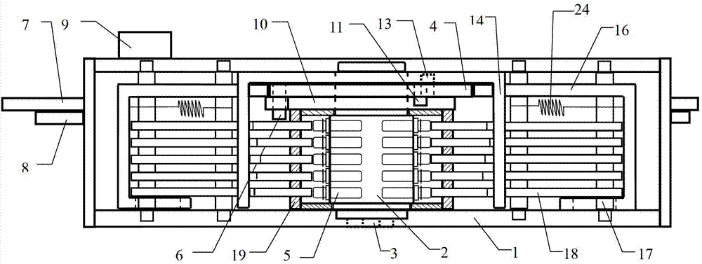
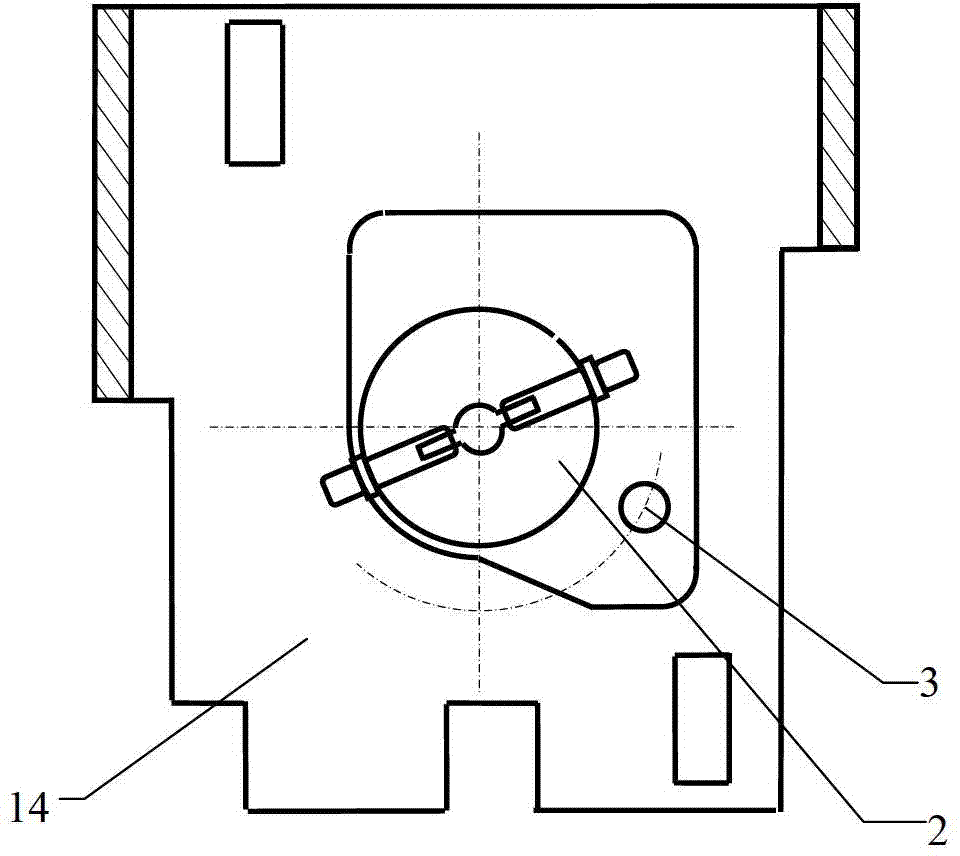
[0021] like figure 1 , figure 2 , image 3 Detent type mechanical anti-theft lock shown:

[0022] 1. The key has tooth flowers on both sides and a column in the middle. There are 5 positions on each side of the tooth flower design, a total of 10 positions. The maximum height difference between each position of this scheme is 2.5mm, and the step difference is 0.5mm. There are 6 optional heights for each position: 0.0mm, 0.5mm, 1.0mm , 1.5mm, 2.0mm, 2.5mm, the key amount is 6 to the 10th power, that is, 60.46 million.

[0023] 2. The lock cylinder 2 is located at the center of the lock body 1 and is rotatable, and ten lock cylinder pins 5 are installed therein. There is a protective ring 19 around the lock cylinder 2, which is fixed on the lock body 1. The protruding ends of the two sets of slides 18 are inserted into the protectiv...


PUM


Abstract

The invention relates to a clamping type mechanical antitheft lock, which comprises a lock body, a lock cylinder, a transmission mechanism, a spring bolt, a lock bolt and a matched key, wherein a protection ring is arranged between the lock body and the lock cylinder; one end of each of a plurality of sliding sheets is inserted into the protection ring; openings are formed in the upper edges of the sliding sheets; before the lock is unlocked, a ball of the lock cylinder is in no contact with the sliding sheets; when the lock cylinder rotates preliminarily, the ball of the lock cylinder is in contact with the sliding sheets and pushes the sliding sheets to the openings in the upper edges to form a straight line; during rotation of the lock cylinder, the ball in the lock cylinder is separated from the sliding sheets, and then a shifting pin A on a cam fixed at one end of the lock cylinder drives a stopping plate to downwards move and be clamped in the openings of the sliding sheets, so that the lock cylinder can continuously rotate and sequentially drive a swing rod, the lock bolt and the spring bolt to move; and therefore, unlocking operation can be finished.

Description

technical field [0001] The invention relates to a mechanical anti-theft lock, in particular to a snap-position type mechanical anti-theft lock. Background technique [0002] A mechanical lock is generally composed of a lock body, a lock cylinder, a transmission mechanism, a lock tongue, and a lock bolt. The lock cylinder is the key component, which contains the lock cylinder tumbler group. The movement and movement range of the pins of the lock cylinder are determined by the key. Only when the correct key is encountered, the pins of the lock cylinder can move to the correct position, and the lock cylinder can rotate or move in other forms, and then drive the transmission mechanism to complete the unlocking action. The mechanical locks on the market, no matter how they change, most of the locks have a common feature in their design, that is, before the unlocking mechanism is activated, each pin group (or parts such as blades) and other related unlocking actuators are always ...

Claims


Application Information

Patent Timeline
IPC IPC(8): E05B31/00E05B17/20
Inventor 吕雪寒叶延亮徐忠顺曹俊标房丽敏
Owner 如东县岔河污水处理有限公司
Learn More