Energy reducer for drainage system of house building

A technology of building drainage and energy reducer, applied in the direction of pipes/pipe joints/pipe fittings, mechanical equipment, pipe components, etc., can solve the problems of small inspection opening, deformation of energy dissipation device, small impact energy, etc., to achieve convenient cleaning and inspection, Sealed connection and firm, easy-to-clean effect

Active Publication Date: 2013-01-23
ZHEJIANG TONGZHENG PIPE TECH
View PDF9 Cites 5 Cited by
  • Summary
  • Abstract
  • Description
  • Claims
  • Application Information

AI Technical Summary

Problems solved by technology

[0005] 1. Only 1 / 2 of the high-speed flowing water falling from the main standpipe passes through the upper water flow baffle, forming a recoiled water film deflection, and the remaining 1 / 2 of the water needs to rely on the water film recoiled by the baffle The baffle flow disturbs the mixing, the buffering effect is not obvious, and the asymmetric design of the curved baffle, in the long-term use process, it is easy to deform the energy dissipation device due to the impact of the water flow;
[0006] 2. The main body of the energy dissipator and the cover plate are glued together. When the energy dissipator is blocked, the cover of the inspection port can only be opened to clear it. However, the inspection port in this invention is very small. When the blockage is relatively large, Unable to clean up;
But because in the actual use process, the probability of recoil water hitting the inner wall of the main body is small, so in many cases the soft rubber coated on the inner wall of the main body cannot consume the kinetic energy of the water flow; even when the water flow recoils to the inner wall, its impact force is already large The range is reduced, and the impact energy consumed by the soft rubber inside the main body is also very small, but the overweight soft rubber will inevitably increase the weight and cost of the main body, and bring a certain burden on the drainage riser

Method used


Image

  • Energy reducer for drainage system of house building
  • Energy reducer for drainage system of house building
  • Energy reducer for drainage system of house building

Examples


Embodiment Construction

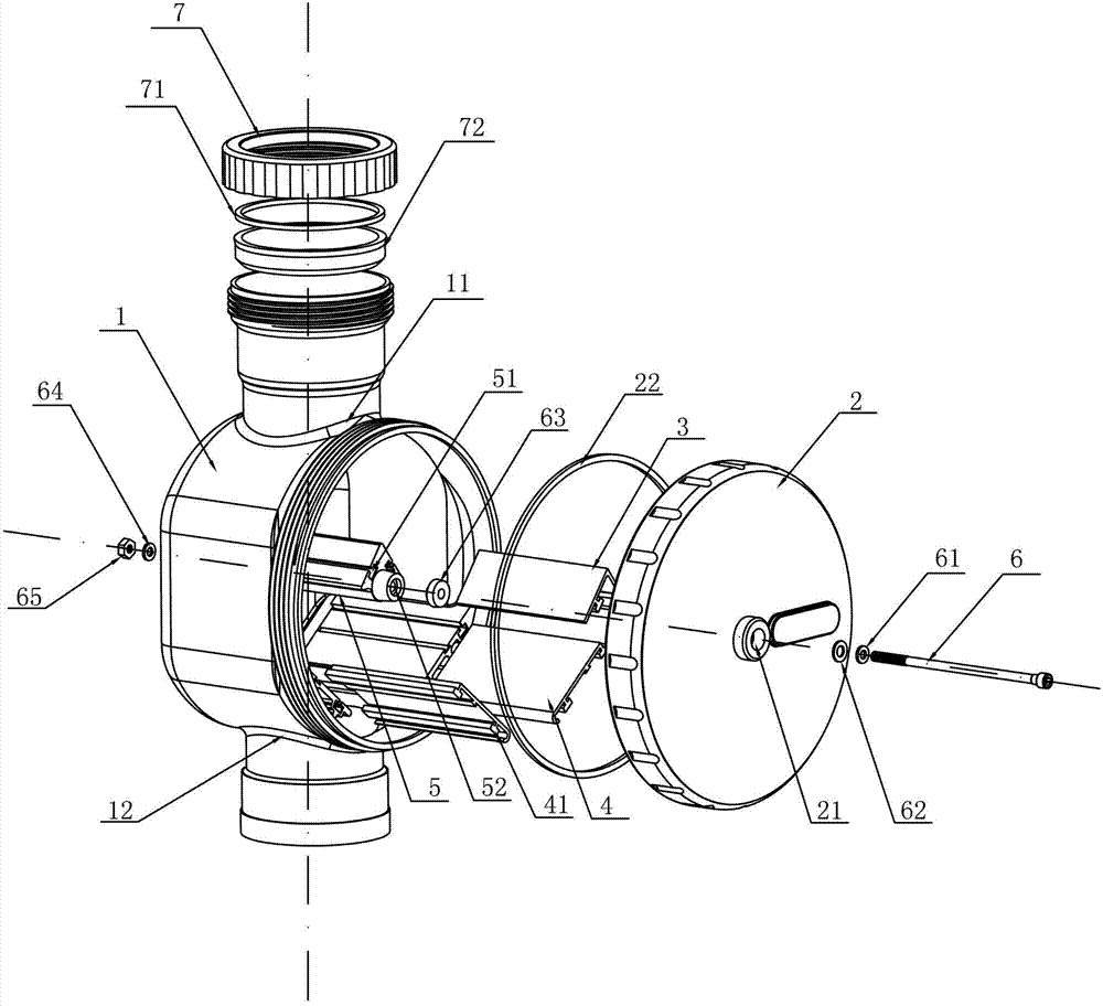
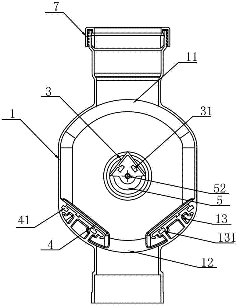
[0036] Such as figure 1 with figure 2 As shown, an energy absorber for a building drainage system includes a main body 1, a sealing cover 2, and a first buffer plate 3, a second buffer plate 4, and a support column 5 arranged in the main body 1; wherein, the support column 5 One end is fixed at the center of the inner wall of the main body 1, and the other end is screwed on the sealing cover 2; the first buffer plate 3 is in an inverted "V" shape and is arranged on the support column 5; the energy absorber includes two second buffer plates Plate 4 and the second buffer plate 4 are symmetrically installed on the inner wall of the lower end of the main body 1; the upper end of the main body 1 is provided with a drainage riser inlet 11 communicating with the inner cavity of the main body, and the lower end of the main body 1 is provided with a drainage pipe connected with the inner cavity of the main body. The riser is connected to the outlet 12 , and the sealing cover 2 is scr...


PUM


Abstract

The invention discloses an energy reducer for a drainage system of a house building, and belongs to the field of building drainage systems. The energy reducer comprises a main body, a sealing cover, as well as a first buffer board, two second buffer boards and a support pillar which are arranged in the main body, wherein one end of the support pillar is fixed at the circle center of the inner wall of the main body, and the other end of the support pillar is in threaded connection with the sealing cover; the first buffer board is inverted-V-shaped and is arranged on the support pillar; the two second buffer boards are symmetrically arranged on the inner wall of the lower end of the main body; a vertical drainage pipe inlet is arranged at the upper end of the main body and is communicated with the inner cavity of the main body, and a vertical drainage pipe outlet is arranged at the lower end of the main body and is communicated with the inner cavity of the main body; and the sealing cover is in threaded connection with one side surface of the main body. The energy reducer with the structure has the advantages of having an obvious buffer effect and a good noise prevention effect, being convenient to assemble and disassemble, light in weight and long in service life, and the like.

Description

technical field [0001] The invention relates to an energy reducer for building drainage systems, belonging to the field of building drainage systems. Background technique [0002] Pipes made of rigid polyvinyl chloride (U-PVC) as the main raw material have the advantages of light weight, corrosion resistance, small water flow resistance, convenient installation, low cost, and energy saving. Therefore, the drainage systems of many high-rise buildings are currently Rigid PVC drain riser is used. However, due to the high floor and large drop of high-rise buildings, the water flow falls fast and has a large kinetic energy, which has a large impact on the drainage riser, especially the drainage riser at the bottom of the building, which is likely to cause deformation or rupture of the pipe. Therefore, in the actual installation process, it is necessary to install an energy-reducing (or energy-dissipating) device on the drainage standpipe. Its main functions are: to reduce the im...

Claims


Application Information

Patent Timeline
Patent Type & Authority Applications(China)
IPC IPC(8): F16L55/02
Inventor 钱功海
Owner ZHEJIANG TONGZHENG PIPE TECH
Why Eureka
Try Eureka