Side lighting device engaged with medullary cavity guide needle

A side-emitting and jointing device technology, which is applied to lighting devices, components of lighting devices, electric light sources, etc., can solve problems such as device failure, high power consumption, and physical injury

Active Publication Date: 2013-01-23
朱唯勤
View PDF4 Cites 2 Cited by
  • Summary
  • Abstract
  • Description
  • Claims
  • Application Information

AI Technical Summary

Problems solved by technology

[0006] Although the above-mentioned two inventions use internal lighting to locate the operation steps, which reduces the risk of additional injuries and increases the convenience of the operation, because the light source is designed at the front end of the guide pin, the light mainly travels in the longitudinal direction, which cannot Effective lateral divergence leads to a very weak light source observed by the operator, and it is often necessary to increase the power of the light source, resulting in high power consumption or high temperature due to high light intensity, which will cause damage to the body.
[0007] Moreover, although the above-mentioned structure of the prior art of the U.S. Patent Office digs a hole laterally to allow the light source to emit from the side end, this design instead makes the position of the light source form an open structure. During the operation, it is easy for the lighting device to be infiltrated by body fluids, causing the device to malfunction and even contaminate the affected part
[0008] And because the lighting device and the guide pin of the medullary cavity are fixed and integrally formed, it needs to be individually designed and manufactured for different brands of the guide pin of the medullary cavity, and the cost is relatively high. The entire set of devices is discarded together, resulting in a waste of resources; moreover, because the lighting device is located at the front end of the medullary canal guide wire, during the operation, the medullary canal guide wire must go deep into the bone marrow cavity, and the bulb has no protection during the operation. device, prone to bulb damage in the medullary cavity due to collision with bony tissue

Method used


Image

  • Side lighting device engaged with medullary cavity guide needle
  • Side lighting device engaged with medullary cavity guide needle
  • Side lighting device engaged with medullary cavity guide needle

Examples


Embodiment Construction

[0031] The following will clearly and completely describe the technical solutions in the embodiments of the present invention with reference to the accompanying drawings in the embodiments of the present invention. Obviously, the described embodiments are only some, not all, embodiments of the present invention. Based on the embodiments of the present invention, all other embodiments obtained by persons of ordinary skill in the art without creative efforts fall within the protection scope of the present invention.

[0032] Hereinafter, examples of the method of the present invention will be specifically described.

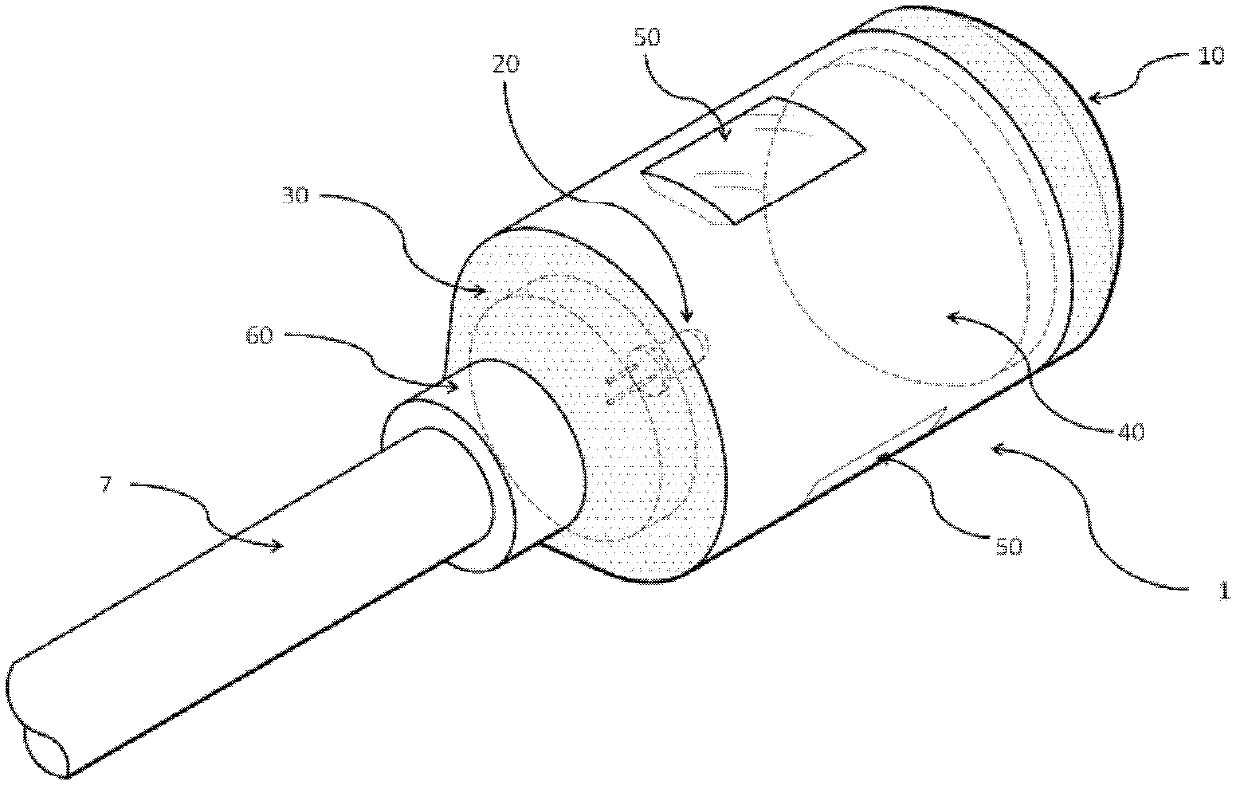
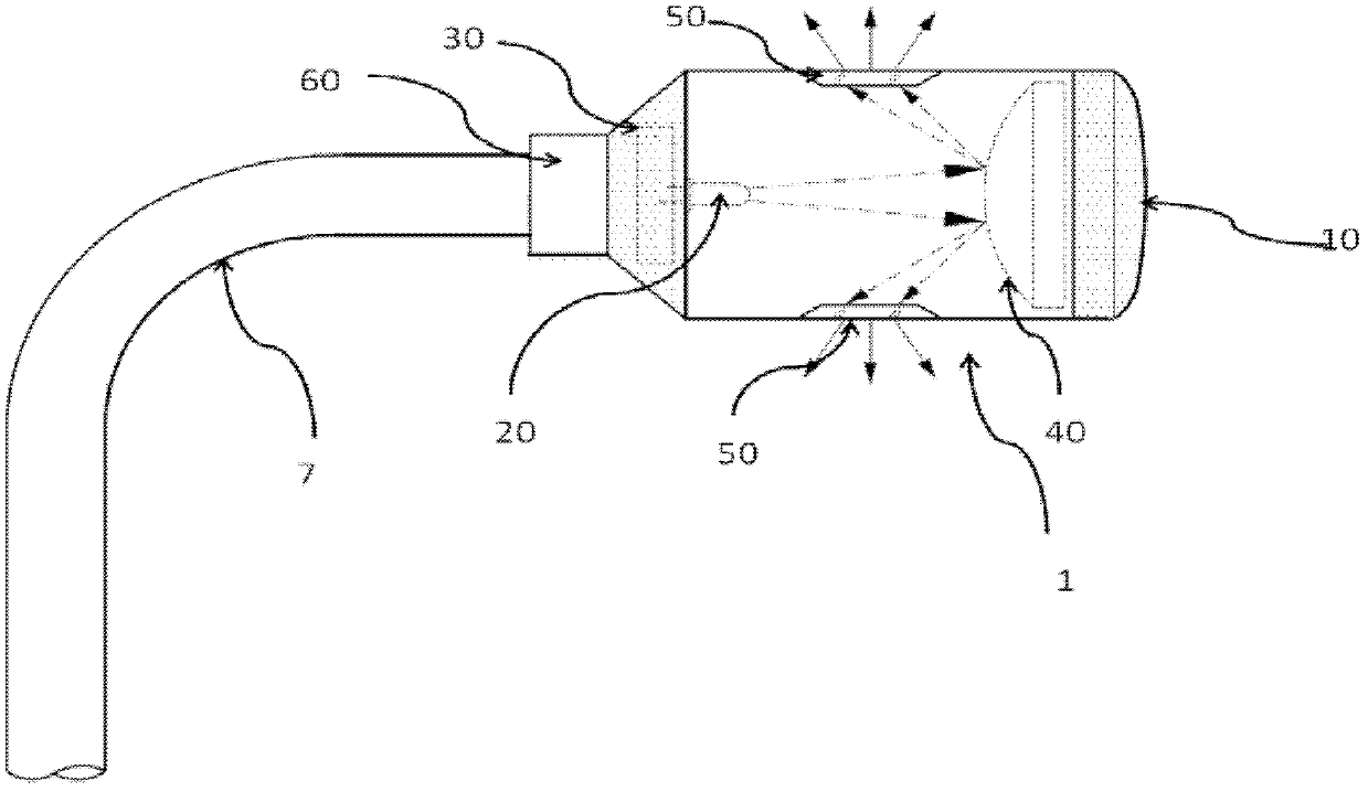
[0033] Such as figure 1 As shown, in the embodiment of the present invention, a lateral light-emitting device engaged with a medullary canal guide wire includes: a main body 1, and the interior of the main body 1 is designed as a hermetic accommodating space as a whole, so that the lateral light emitting device of the present invention When the light-emitting devi...


PUM


Abstract

The invention discloses a side lighting device engaged with a medullary cavity guide needle. The device substantially comprises a sealed body, a front-end protection unit arranged at a front end of the body, and an engagement unit arranged at a rear end of the body. A lighting unit, a power supply unit, a light scattering unit, a light source intensity regulation unit and a light transmission window are arranged inside the body. According to an embodiment of the invention, the side lighting device can be movably combined with different medullary cavity guide needles and the lighting unit is powered by the power supply unit, so that the light generated by the lighting unit is subjected to scattering by the light scattering unit or further subjected to proper intensity regulation, and radiates sideways through the light transmission window; and while performing a steel nail operation in a medullary cavity, the device of the invention can be disposed inside affected parts, thereby achieving the external observation of the operation position and the accurate positioning of the steel nails.

Description

technical field [0001] The invention relates to the design and technical field of a medullary cavity guide pin, and in particular relates to a lateral light-emitting device that can be engaged with a medullary cavity guide pin. Background technique [0002] In the past two decades, most lower limb fractures and some upper limb fractures have been treated clinically with so-called intramedullary nail fixation. The insertion of the steel nail needs to be guided by a medullary cavity guide wire, and then the sleeve-shaped steel nail is placed outside the medullary cavity guide wire, and slowly and carefully inserted into the bone marrow cavity along its guide. [0003] However, in the operation of fixing the two ends of the steel nail with screws, the more difficult part of this method is to find the positions of the fixing holes at the two ends of the steel nail in the affected part, so as to drill holes on the bone to fix the steel nail. Since the steel nail has been implant...

Claims


Application Information

Patent Timeline
Patent Type & Authority Applications(China)
IPC IPC(8): F21S9/02F21V13/04F21V17/00A61B17/68F21W131/20
Inventor 朱唯勤曾尹俊朱唯廉
Owner 朱唯勤
Why Eureka
Try Eureka