Lightning protection and harmonic elimination reactive power compensation capacitive transformer

A technology of power compensation and transformer, applied in reactive power adjustment/elimination/compensation, reactive power compensation, transformer/inductor coil/winding/connection, etc., can solve the problem of energy saving, harmonic amplification, capacitive transformer application restrictions, etc.

Active Publication Date: 2016-03-02
尤大千
View PDF5 Cites 0 Cited by
  • Summary
  • Abstract
  • Description
  • Claims
  • Application Information

AI Technical Summary

Problems solved by technology

Attaching it inside the transformer unnecessarily reduces the reliability of the transformer
[0012] (3) Such a transformer structure cannot effectively suppress high-order harmonics, and it will cause harmonic amplification for most low-frequency harmonics
And it is also impossible to implement automatic adjustment of reactive power compensation according to the change of load
Not only increase the cost, but also cause reactive power overcompensation, which is not conducive to energy saving
[0015] (2) When the voltage on one side of the transformer is EHV or UHV, it is difficult for the capacitive winding to withstand extremely high electric field strength
Therefore, the application of capacitive transformers is limited
[0016] (3) The low-voltage isolation transformer adopts Wiring mode, when the load on the secondary side is unbalanced, a high zero-sequence potential will appear, resulting in asymmetric potential of each phase

Method used


Image

  • Lightning protection and harmonic elimination reactive power compensation capacitive transformer
  • Lightning protection and harmonic elimination reactive power compensation capacitive transformer
  • Lightning protection and harmonic elimination reactive power compensation capacitive transformer

Examples


Embodiment Construction

[0061] Below in conjunction with accompanying drawing and embodiment the present invention is described in further detail

[0062] First, the structure of the capacitive winding of the present invention will be described.

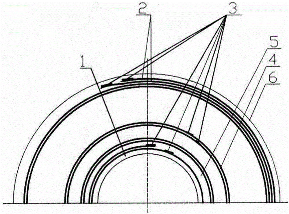
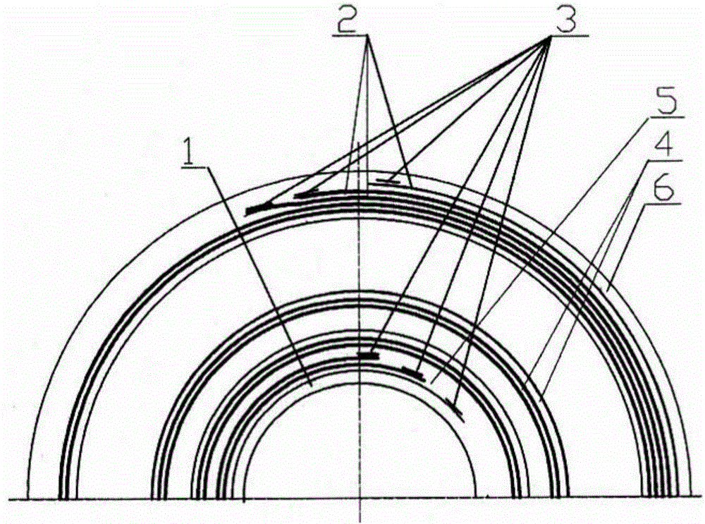
[0063] Figure 1a This is the structure of the foil-type double-stack capacitive winding of the present invention. In the present invention, one layer of insulating layer 4, one layer of metal foil 2, another layer of insulating layer 4, and another layer of metal foil 2 are separated from each other and stacked, and wound on the inner insulating cylinder 1 (the inner insulating cylinder 1 is also may be formed by the first insulating layer 4 itself). After the winding is completed, an outer insulating layer 6 is wrapped on the surface of the outer metal foil 2 of the winding. (It is also possible to place the metal foil 2 in the innermost layer, thicken the outer insulating layer 4 after winding to naturally form the outer insulating layer 6 of the wind...


PUM


Abstract

The invention provides a lightning protection and resonance elimination reactive power compensation capacity transformer which comprises an iron core. The lightning protection and resonance elimination reactive power compensation capacity transformer is characterized in that a work winding at each voltage side on each phase of iron core column of the transformer is insulated and wound by adopting a single-layer metal foil or single-turn conductor; each winding on each phase of iron core column of a first independent additional winding, a second independent additional winding, a third independent additional winding, a fourth independent additional winding, a fifth independent additional winding or a sixth independent additional winding is insulated by using two layer or three layer of metal coils to be lapped together to form two or three concentric coils, namely a foil type double-lapped winding or foil type triple-lapped winding; and the input number or coil number of the additional windings are automatically switched by adopting manual switching or a factor automatic compensation device according to the change condition of load power factors. The lightning protection and resonance elimination reactive power compensation capacity transformer has the advantages of safety, reliability and excellent energy-saving effect and is used for ultrahigh and superhigh voltage products; and the harmonic pollution and power energy loss in power transmission and transformation facilities are reduced.

Description

technical field [0001] The invention relates to a transformer for power step-up and step-down, power distribution, rectification and electronic equipment isolation power supply, in particular to a reactive power compensation capacitive transformer for lightning protection and harmonic elimination. Background technique [0002] At present, the connection of three-phase transformer windings is nothing more than Y (including Y 0 ) connection, Δ connection and Z (including Z 0 ) in three ways. [0003] For the three-phase double-coil distribution transformer that supplies power to users in the high-voltage power grid, when the secondary low-voltage power grid adopts a three-phase four-wire (TN-S or TN-C-S) system for power distribution, the commonly used wiring methods are Y / Y 0 and Δ / Y 0 Two kinds. where Y / Y 0 The transformer of the connection mode is relatively low in manufacturing cost. But the zero-sequence impedance is larger. When a single-phase ground short circuit...

Claims


Application Information

Patent Timeline
Patent Type & Authority Patents(China)
IPC IPC(8): H01F27/30H01F27/28H02J3/18
CPCY02E40/30
Inventor 尤大千
Owner 尤大千
Why Eureka
Try Eureka