
Method for deicing by using power circuit deicing device

A technology for power lines and deicers, used in cable installation, electrical components, overhead installation, etc., can solve problems such as the weakening of the bearing capacity of line towers or poles, endangering the safety of operators, and the collapse of line towers or poles. , to achieve the effect of large impact force, good deicing effect and large deicing area

Active Publication Date: 2013-01-23
STATE GRID CORP OF CHINA +2
View PDF2 Cites 6 Cited by
  • Summary
  • Abstract
  • Description
  • Claims
  • Application Information

AI Technical Summary

Problems solved by technology

At present, there are mainly two methods for clearing ice on the line: first, the manual clearing method, the operator manually clears it through a manned tackle. This method has the defects of high labor intensity and low safety factor. The weight of the line tower or line pole is weakened. If the operator goes up, it is easy to cause the line tower or line pole to collapse, endangering the life of the operator; second, using small mechanical deicing, although this method overcomes the above defects , but affected by the geographical location and the surrounding environment, it is difficult to transport the machinery up in the mountainous environment, and the freezing weather does not exist for a long time, and even a major freezing disaster occurs once every few years. The machinery needs long-term maintenance, and the maintenance cost is huge. Increase

Method used


Image

  • Method for deicing by using power circuit deicing device
  • Method for deicing by using power circuit deicing device
  • Method for deicing by using power circuit deicing device

Examples


Embodiment Construction

[0040] The structure and operating principle of the power line deicer of the present invention will be further described in detail below in conjunction with the accompanying drawings.

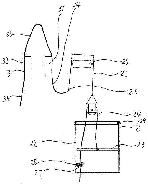
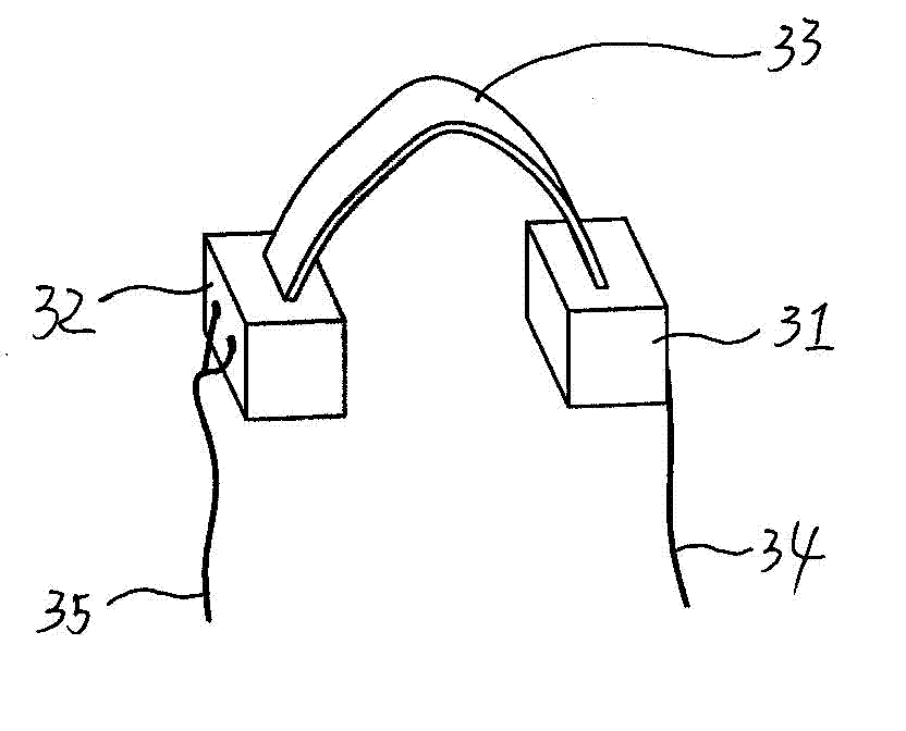
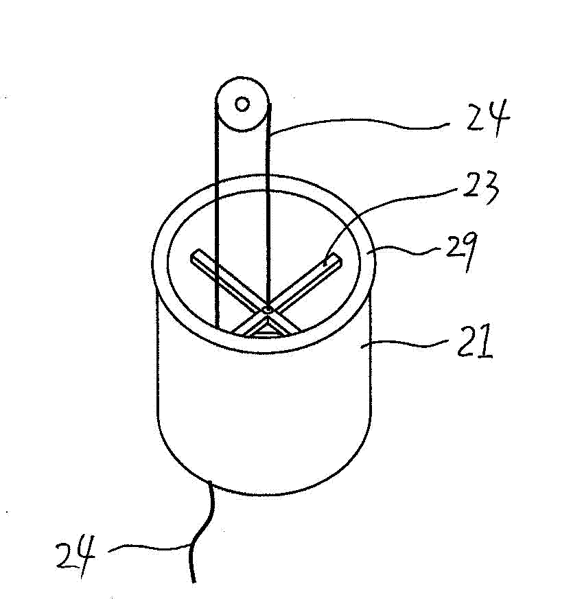
[0041] Such as figure 1 , figure 2 with image 3 As shown, the structure diagram of the power line deicer of the present invention includes a hanging point removal mechanism 3 and a deicing mechanism 2, and the hanging point removal mechanism 3 includes two hanging point removal hammers 31, 32, and the two hanging point removal hammers 31 , 32 are provided with connecting rope 33, are connected with sag rope 34,35 below hanging point removal hammer 31,32, and deicing mechanism 2 comprises somersault block 21 and deicing cylinder 22, closes in deicing cylinder 22 The middle position is provided with a suspension bracket 23, and the suspension bracket 23 is fixed with a stay rope 24 that bypasses the somersault block 21. The suspension end 25 of the somersault block 21 is connected with the sa...


PUM


Abstract

The invention belongs to the technical field of methods for removing ice coated on a lead, and discloses a method for deicing by using a power circuit deicing device. The device is mainly and technically characterized by comprising a mount point cleaning mechanism and a deicing mechanism, wherein the mount point cleaning mechanism comprises two mount point cleaning hammers and a connecting rope, and an arc hanging rope is connected below each mount point cleaning hammer; the deicing mechanism comprises a following tackle and a deicing barrel, wherein a hanging bracket is arranged at a position close to the middle part in the deicing barrel, a pull rope which can bypass the following tackle is fixedly arranged on the hanging bracket, and a hanging end of the following tackle is connected with the arc hanging rope of one mount point cleaning hammer; the method comprises the steps that: firstly, ice coated on a mount point can be removed by using the mount point cleaning hammers; secondly, a running wheel of the following tackle is hung on the mount point, and the coated ice is forcefully impacted by using the deicing barrel, so that the deicing area is large, and the deicing speed is fast; and the mount point, the connecting rope, the deicing barrel and the like can be conveniently carried, all operations can be finished by an operator on the ground, and the safety factor is high.

Description

[0001] [0002] The present invention is a divisional application. The filing date of the original application is: August 11, 2011; the application number of the original application is: 201110229909.0; The ice method. technical field [0003] The invention belongs to the technical field of deicing methods for wires, and in particular relates to a deicing method using a power line deicer. Background technique [0004] When natural disasters such as freezing occur, there will be icing around the conductors of the transmission line. These icings will seriously affect the normal power supply, and in severe cases will cause the tower to collapse or be damaged. Therefore, it must be removed in time. At present, there are mainly two methods for clearing ice on the line: first, the manual clearing method, the operator manually clears it through a manned tackle. This method has the defects of high labor intensity and low safety factor. The weight of the line tower or line pole is ...

Claims


Application Information

Patent Timeline
Patent Type & Authority Applications(China)
IPC IPC(8): H02G7/16
Inventor 李树平张广峻刘明亮张留岗王继双梁河雷何义良刘林青
Owner STATE GRID CORP OF CHINA
Learn More