Flyback constant-current driving circuit and flyback constant-current driving control system containing flyback constant-current driving circuit

A technology of constant current drive and control system, applied in electric lamp circuit arrangement, electric light source, lighting device, etc., can solve the problems of high cost of peripheral circuits, long startup time, etc., to reduce the cost of components, improve efficiency, and reduce startup effect of time

Active Publication Date: 2013-01-23
HANGZHOU SILAN MICROELECTRONICS
View PDF9 Cites 13 Cited by
  • Summary
  • Abstract
  • Description
  • Claims
  • Application Information

AI Technical Summary

Problems solved by technology

[0004] figure 1 In the constant current drive control system shown, the PWM control circuit 10 outputs a pulse signal, which needs to provide a larger drive current to the MOS transistor (usually a high-voltage transistor) M1, so the capacitor C1 must be selected to provide a corresponding larger value. energy, resulting in a longer start-up time for the system at start-up
also, figure 1 The system shown requires power supply from the auxiliary winding of the transformer, and also needs a diode D1, resulting in higher cost of peripheral circuits

Method used


Image

  • Flyback constant-current driving circuit and flyback constant-current driving control system containing flyback constant-current driving circuit
  • Flyback constant-current driving circuit and flyback constant-current driving control system containing flyback constant-current driving circuit
  • Flyback constant-current driving circuit and flyback constant-current driving control system containing flyback constant-current driving circuit

Examples


Embodiment Construction

[0037] The present invention will be further described below in conjunction with specific embodiments and accompanying drawings, but the protection scope of the present invention should not be limited thereby.

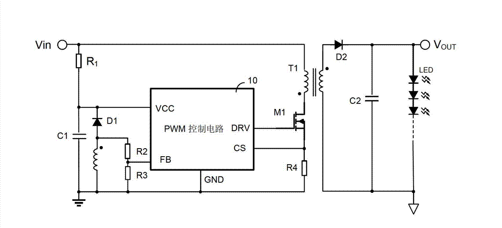
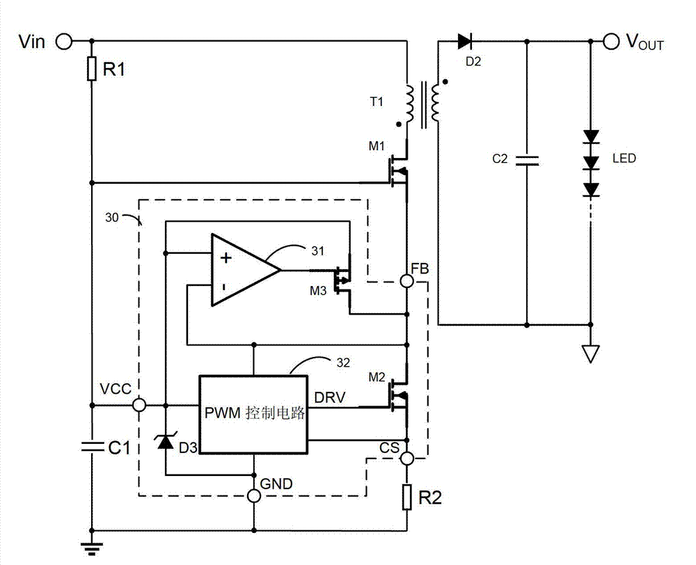
[0038] refer to image 3 , the flyback constant current drive control system of this embodiment includes: flyback constant current drive circuit 30, starting resistor R1, starting capacitor C1, transformer T1, third switch M1, sampling resistor R2, output capacitor C2, load LED .

[0039] Wherein, the first end of the start-up resistor R1 receives the input voltage Vin, and the second end is connected to the first end of the start-up capacitor C1, the power port VCC of the flyback constant current drive circuit 30 and the control end of the third switch M1. The second end of the starting capacitor C1 is grounded. The starting resistor R1 and the starting capacitor C1 are used for starting the flyback constant current drive circuit 30 and supplying power to the flybac...


PUM


Abstract

The invention provides a flyback constant-current driving circuit and a flyback constant-current driving control system containing the flyback constant-current driving circuit. The driving circuit comprises a voltage regulator tube, a PWM (Pulse-Width Modulation) control circuit and a first switch, wherein an anode of the voltage regulator tube is connected with a power supply port and a cathode of the voltage regulator tube is connected with a ground port; the PWM control circuit is connected with the power supply port, the ground port, a feedback port and a sampling port; a driving signal is generated according to a power supply signal received from the power supply port, a feedback signal received from the feedback port and a sampling signal received from the sampling port; a control end of the first switch receives the driving signal, and an input end of the first switch is connected with the feedback port and an output end of the first switch is connected with the sampling port. According to the driving circuit, the starting time is shortened effectively, and peripheral elements are reduced and the system cost is lowered.

Description

technical field [0001] The invention relates to a flyback constant current drive circuit and a flyback constant current drive control system comprising the same. Background technique [0002] figure 1 It shows a traditional flyback constant current drive control system, including: resistor R1, capacitor C1, diode D1, resistor R2, resistor R3, transformer T1 (including primary side, secondary side and auxiliary winding), MOS tube M1, resistor R4, diode D2, output capacitor C2, load LED light string and pulse width modulation (PWM) control circuit 10 . One end of the resistor R1 receives the input voltage Vin, and the other end of the resistor R1 is connected to one end of the capacitor C1 , the cathode of the diode D1 and the power pin VCC of the PWM control circuit 10 . The other end of the capacitor C1 is grounded, the anode of the diode D1 is connected to the same-named end of the auxiliary winding of the transformer T1 and one end of the resistor R2, the opposite end of...

Claims


Application Information

Patent Timeline
Patent Type & Authority Applications(China)
IPC IPC(8): H05B37/02
Inventor 王栋吴建兴
Owner HANGZHOU SILAN MICROELECTRONICS
Why Eureka
Try Eureka