Angle-adjustable fixture for machine tool

An adjustable, angled technology used in clamping, manufacturing tools, metalworking machine parts, etc.

Inactive Publication Date: 2013-01-30
沈阳市东陵区(浑南新区)卓科技术开发中心
View PDF0 Cites 14 Cited by
  • Summary
  • Abstract
  • Description
  • Claims
  • Application Information

AI Technical Summary

Problems solved by technology

[0003] The purpose of the present invention is to provide an angle-adjustable fixture for machine tools, which solves the problem of secondary clamping when machining parts with angular dimensions with the three coordinates of the machine tool, and ensures the machining accuracy of the parts

Method used


Image

  • Angle-adjustable fixture for machine tool
  • Angle-adjustable fixture for machine tool
  • Angle-adjustable fixture for machine tool

Examples


Embodiment Construction

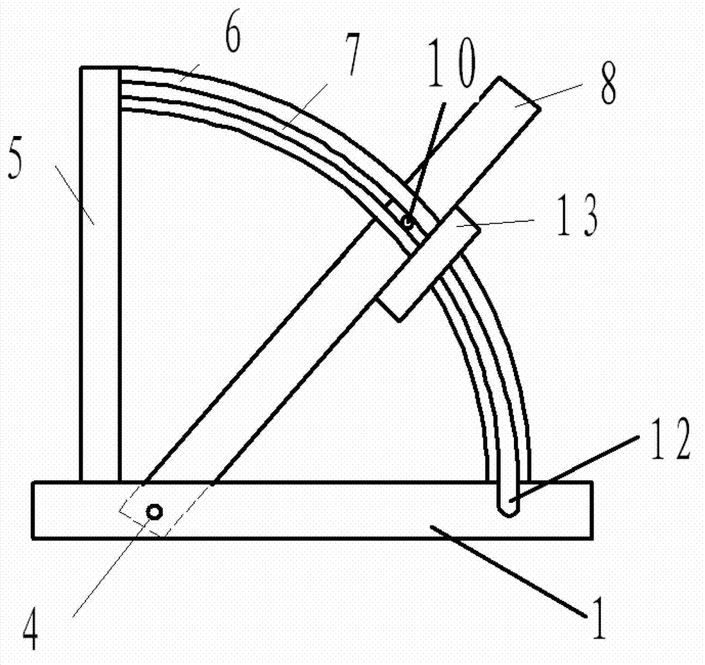
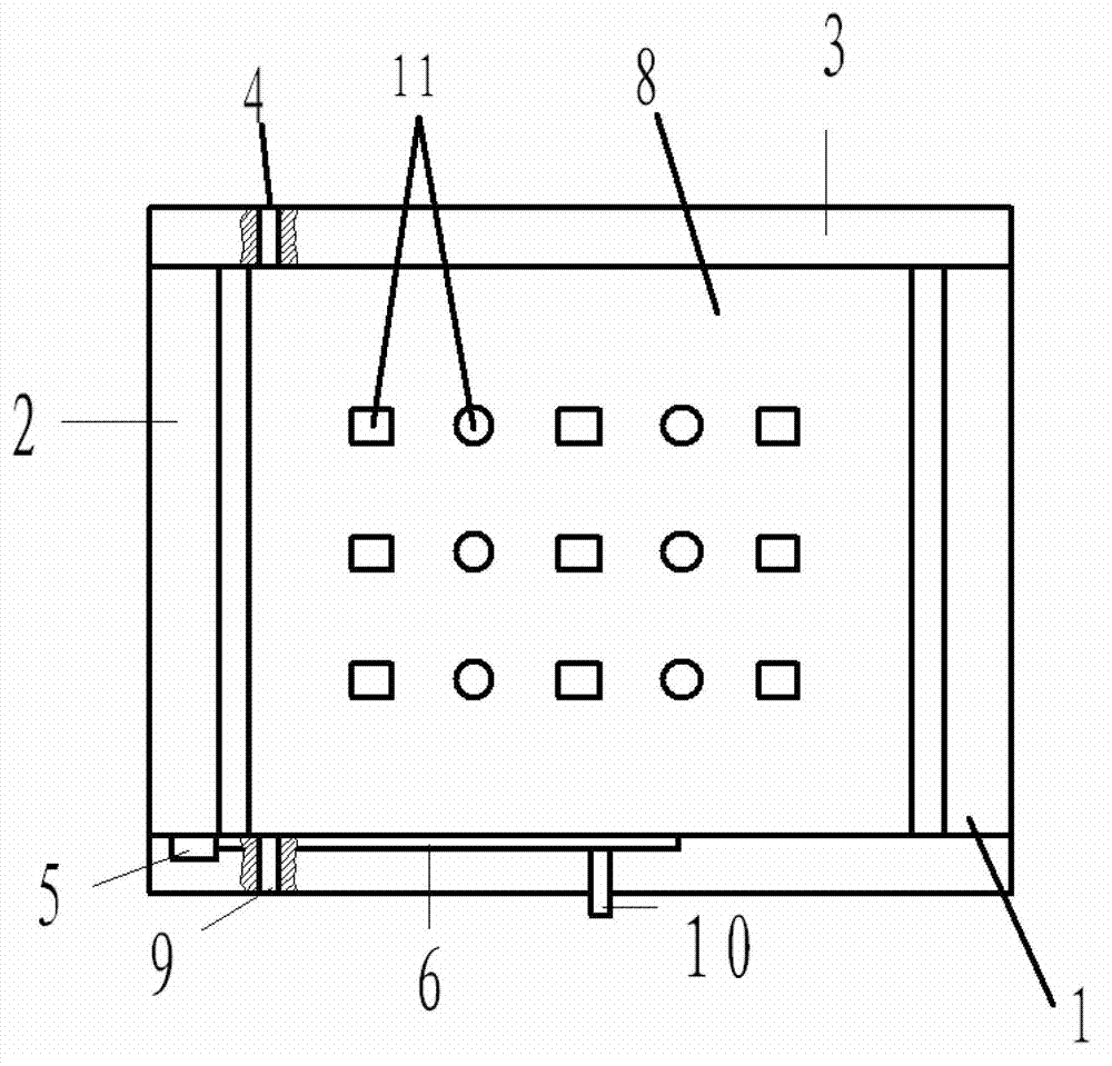
[0020] A kind of specific embodiment of the present invention is described below in conjunction with accompanying drawing, as figure 1 and figure 2 As shown, the present invention includes: a base 1, which can be stably fixed on the machining table of the machine tool. The base 1 is composed of two beams 2 and two plates 3 fixedly connected. Two holes 4 are symmetrically arranged at one end of the two plates 3 , and a support plate 5 is fixedly arranged on the same end of one of the plates 3 . An arc-shaped bracket 6 is provided, the two ends of which are fixedly connected with the plate 3 and the support plate 5 respectively, and an arc-shaped channel 7 is arranged in the arc-shaped bracket 6 . The base 1 is provided with a rotating plate 8, and one end of the rotating plate 8 is symmetrically provided with two shafts 9 installed in the two holes 4, so that it can rotate but cannot produce lateral and longitudinal displacement. A force applying rod 10 is arranged on the r...


PUM


Abstract

The invention relates to an angle-adjustable fixture for a machine tool. The fixture comprises a base and a rotating plate, wherein a required angle can be formed between the rotating plate and the base; and positioning devices are arranged between arc brackets and the rotating plate through support plates on the base. When a part is machined on the common machine tool or a numerical control machine tool with less than three coordinates, a part which has angular dimensions with the three coordinates can be machined, secondary clamping is not needed, machining accuracy is ensured, and the labor intensity of workers is reduced.

Description

technical field [0001] The invention relates to a clamp for machine tools, in particular to an angle-adjustable clamp for machine tools. Background technique [0002] When existing ordinary machine tools and CNC machine tools below three coordinates process parts, the processing range is within the three coordinates of the machine tool, that is, x-axis, y-axis, and z-axis. When the dimensions within the three coordinates are processed and parts with angular dimensions to the three coordinates of the machine tool need to be processed, it cannot be completed at one time, and secondary clamping processing is required, so that the machining accuracy of the parts cannot be accurately guaranteed. Contents of the invention [0003] The object of the present invention is to provide an angle-adjustable fixture for machine tools, which solves the problem of secondary clamping when machining parts having an angular size with the three coordinates of the machine tool, and ensures the ...

Claims


Application Information

Patent Timeline
Patent Type & Authority Applications(China)
IPC IPC(8): B23Q3/06
Inventor 任凯
Owner 沈阳市东陵区(浑南新区)卓科技术开发中心
Why Eureka
Try Eureka