High-voltage capacitor discharging device, method thereof and vehicle

A high-voltage capacitor and charge discharge technology, which is applied in the field of high-voltage capacitors, can solve the problems of long discharge time, increased cost, and non-compliance with safety.

Active Publication Date: 2013-01-30
BYD CO LTD
View PDF5 Cites 11 Cited by
  • Summary
  • Abstract
  • Description
  • Claims
  • Application Information

AI Technical Summary

Problems solved by technology

[0003] In the prior art, there are generally two ways to discharge the charge in the high-voltage capacitor: one is to connect a power resistor with a relatively large impedance in parallel on the high-voltage circuit, and the resistor will discharge it through its own heat as long as there is power on the high-voltage circuit. When the high-voltage power is cut off, the resistor will generally release the charge in the high-voltage capacitor within a long period of time. There are two defects in this method. One is that as long as the high-voltage circuit has power, the resistor will discharge The release will continue to consume energy. The second is that the release takes a long time and does not meet the relevant safety requirements; the other is to add a switch on the basis of passive release, and only control the switch when it is necessary to release The disadvantage of this method is that it not only requires a set of independent control circuit to control the discharge switch, but also needs a set of independent power supply circuit that takes power from the high-voltage capacitor to provide work for the control circuit. Power supply, which makes the circuit more complicated, which not only increases the space, but also increases the cost

Method used


Image

  • High-voltage capacitor discharging device, method thereof and vehicle
  • High-voltage capacitor discharging device, method thereof and vehicle

Examples


Embodiment Construction

[0019] In order to make the technical problems, technical solutions and beneficial effects solved by the present invention clearer, the present invention will be further described in detail below in conjunction with the accompanying drawings and embodiments. It should be understood that the specific embodiments described here are only used to explain the present invention, not to limit the present invention.

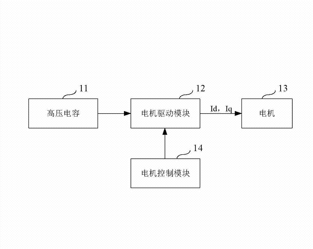
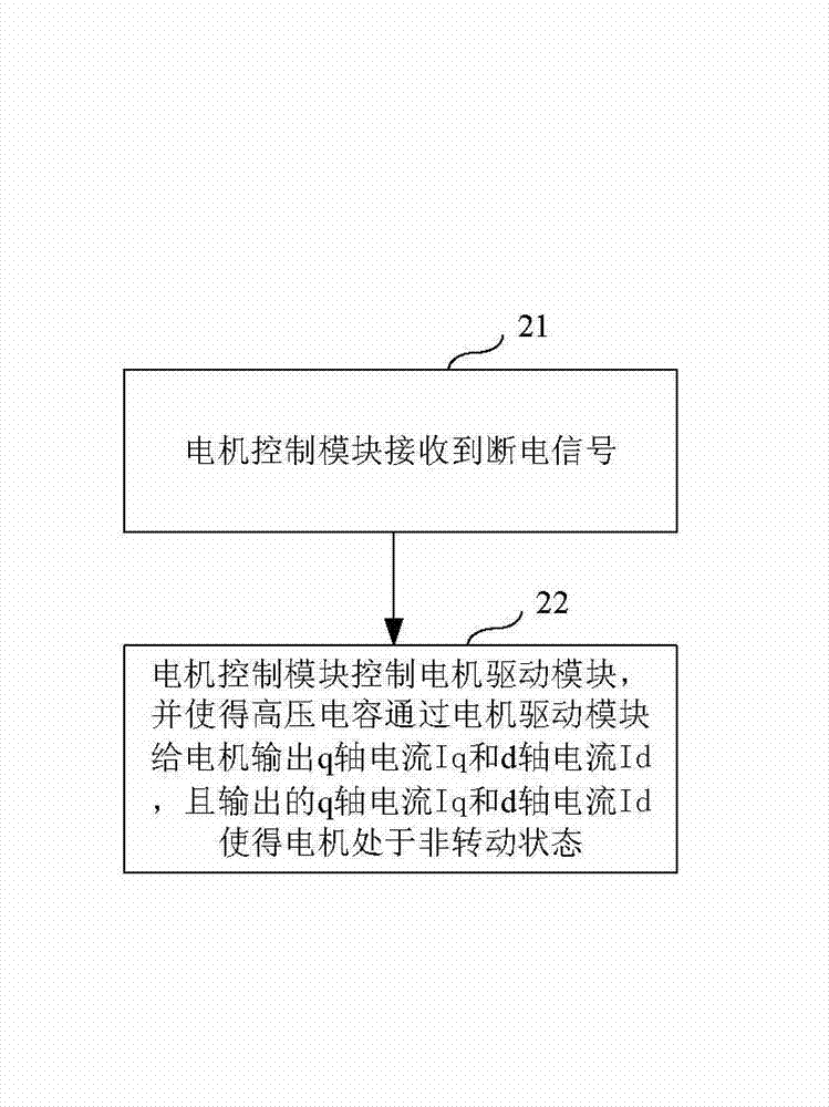
[0020] It is known from the prior art that the motor has a q-axis and a d-axis, wherein, when the current applied on the q-axis reaches a certain value (the certain value is different for different motors, which can be obtained through experiments and calculations), the motor It will produce rotation, and applying any large current on the d-axis will not cause the motor to rotate, but it will still consume energy.

[0021] The applicant of the present invention is based on the above theoretical knowledge, and through his own creative work, he finally thought of a solutio...


PUM


Abstract

A high-voltage capacitor discharging device comprises a motor control module, a motor driving module and a motor, wherein the motor driving module is connected with a high-voltage capacitor, the motor control module and the motor respectively. The motor control module is used for controlling the motor driving module to enable the high-voltage capacitor to output q-shaft current Iq and d-shaft current Id upon reception of a high-voltage outage signal, and the output q-shaft current Iq and the output d-shaft current Id enable the motor not to be in a rotating state. The high-voltage capacitor discharging device enables the charge of the high-voltage capacitor to be automatically discharged via consumption of the motor, but does not lead the motor to run.

Description

technical field [0001] The invention belongs to the field of high-voltage capacitors, and in particular relates to a high-voltage capacitor charge discharge device, a method thereof, and a vehicle. Background technique [0002] When the vehicle is powered off at high voltage (for example, in abnormal situations such as a vehicle collision), there is a large amount of charge in its high-voltage capacitor. If the charge cannot be quickly discharged, it will cause a certain safety hazard to the vehicle. [0003] In the prior art, there are generally two ways to discharge the charge in the high-voltage capacitor: one is to connect a power resistor with a relatively large impedance in parallel on the high-voltage circuit, and the resistor will discharge it through its own heat as long as there is power on the high-voltage circuit. When the high-voltage power is cut off, the resistor will generally release the charge in the high-voltage capacitor within a long period of time. Ther...

Claims


Application Information

Patent Timeline
Patent Type & Authority Applications(China)
IPC IPC(8): B60L3/00
Inventor 周伟杨广明谢洁江汤小华张鑫鑫李英涛
Owner BYD CO LTD
Why Eureka
Try Eureka