Electrolytically-controlled micro-component picking and placing device and method
A pick-and-place device and micro-component technology, applied in the direction of electrolytic components, electrolytic process, manufacturing tools, etc., to achieve the effect of real-time control
- Summary
- Abstract
- Description
- Claims
- Application Information
AI Technical Summary
Problems solved by technology
Method used
Image
Examples
specific Embodiment approach 1
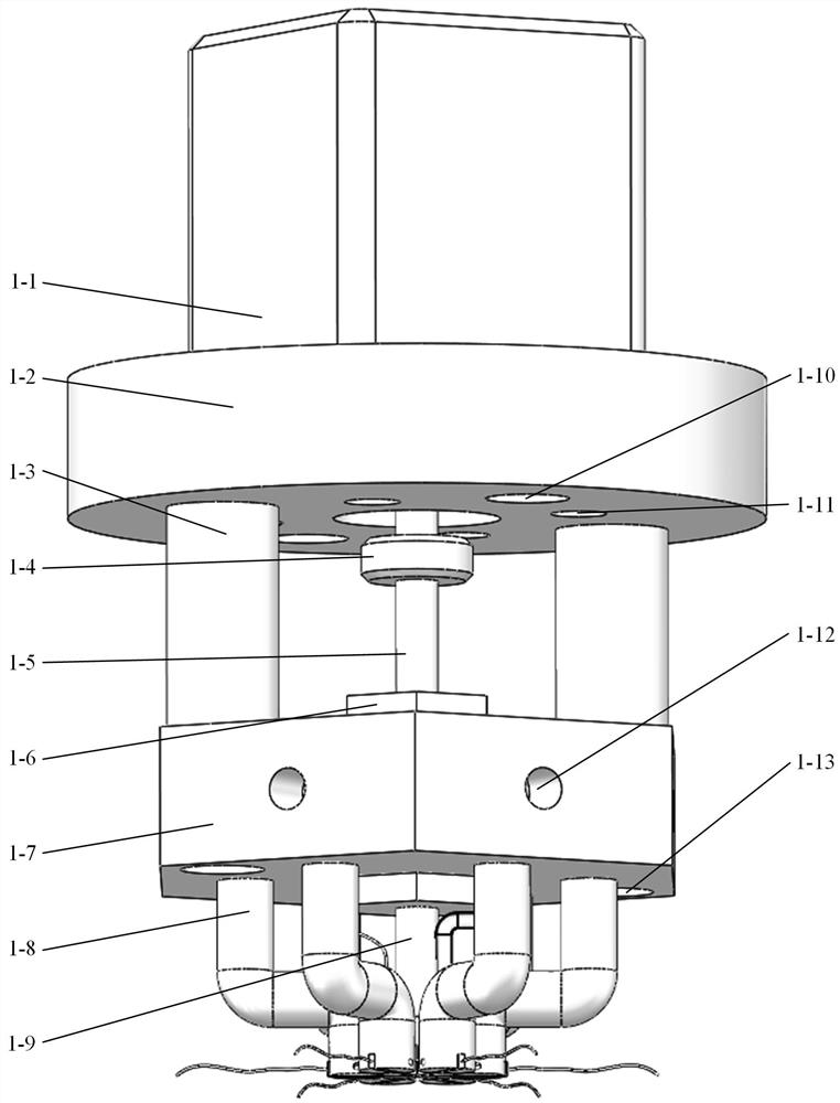
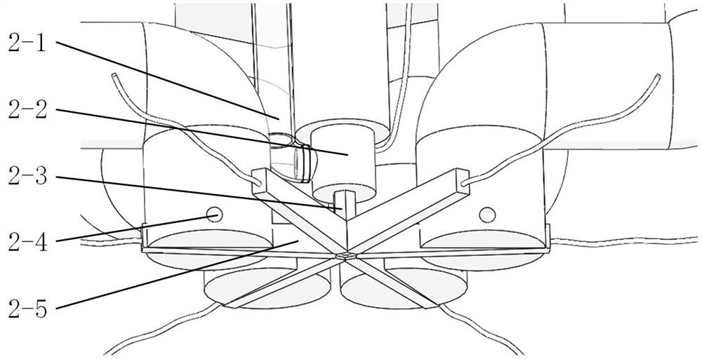
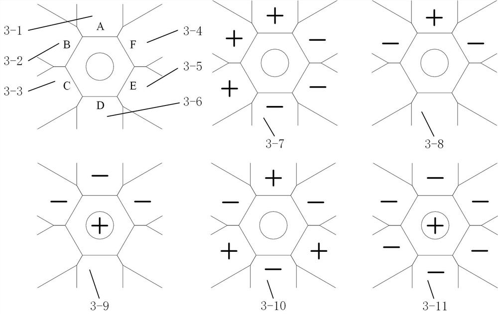
[0016] Specific implementation mode one: combine figure 1 , figure 2 , image 3 and Figure 4 Explain that the micro-component pick-and-place device described in this embodiment includes a micro-drive motor 1-1, a mounting frame 1-2, two sleeves 1-3, a shaft coupling 1-4, a ball screw 1-5, a connecting Nut 1-6, hexagonal mounting frame 1-7, six fixed frames 1-8, long connecting rod 1-9, hose 2-1, electrode connector 2-2, movable electrode 2-3, six The inert electrode 2-5, the mounting frame 1-2 and the micro drive motor 1-1 are connected by bolts through four through holes 1-11, and the micro drive motor 1-1 and the ball screw 1-5 are connected by a coupling 1-1 4. Fixed connection, the connecting nut 1-6 passes through the inner hexagonal hole of the hexagonal mounting frame 1-7, the upper end is threaded with the ball screw 1-5, and the lower end is threaded with the long connecting rod 1-9, and the long connecting rod 1-9 is threaded. The lower end of the rod 1-9 is th...
specific Embodiment approach 2
[0017] Specific implementation mode two: combination figure 1 , figure 2 , image 3 and Figure 4 Note that the connection nut 1-6 in this embodiment fits in clearance with the inner hexagonal hole of the hexagonal mounting frame 1-7, and the upper end of the movable electrode 2-3 interferes with the lower end of the electrode connector 2-2. The ball screw 1-5, the connecting nut 1-6, the inner hexagon hole of the hexagonal mounting frame 1-7, the long connecting rod 1-9, the electrode connector 2-2 and the movable electrode 2-3 are arranged coaxially. Such setting facilitates the assembly and the up and down movement of the movable electrodes 2-3, and other components and connections are the same as those in the first embodiment.
specific Embodiment approach 3
[0018] Specific implementation mode three: combination figure 1 , figure 2 , image 3 and Figure 4 Note that the upper planes and lower bottom surfaces of the six inert electrodes 2-5 in this embodiment are not parallel, and the longitudinal thickness gradually increases from the outside to the inside, and reaches the maximum at the contact with the movable electrodes 2-3. Such arrangement facilitates the alignment between the six inert electrodes 2-5 and the micro-components 4-2 and the observation of the shape of the liquid bridge, and the other components and connections are the same as those in the first or second embodiment.
[0019] Specific implementation mode four: combination figure 1 , figure 2 , image 3 and Figure 4 Description, the mounting frame 1-2, two sleeves 1-3, connecting nuts 1-6, hexagonal mounting frame 1-7, six fixing frames 1-8, and electrode connectors 2-2 described in this embodiment All materials are aluminum alloy, the material of the lo...
PUM
 Abstract
Description
Claims
Application Information
 - R&D
- Intellectual Property
- Life Sciences
- Materials
- Tech Scout
- Unparalleled Data Quality
- Higher Quality Content
- 60% Fewer Hallucinations
Browse by: Latest US Patents, China's latest patents, Technical Efficacy Thesaurus, Application Domain, Technology Topic, Popular Technical Reports.
© 2025 PatSnap. All rights reserved.Legal|Privacy policy|Modern Slavery Act Transparency Statement|Sitemap|About US| Contact US: help@patsnap.com


