Activated sludge reaction system

A technology of reaction system and activated sludge, applied in water/sludge/sewage treatment, biological water/sewage treatment, sustainable biological treatment, etc., can solve the problem of high energy consumption of water inflow, and achieve the effect of ensuring continuity

Active Publication Date: 2013-01-30
SHENZHEN DEWEI INTELLIGENT MFG TECH CO LTD
View PDF2 Cites 0 Cited by
  • Summary
  • Abstract
  • Description
  • Claims
  • Application Information

AI Technical Summary

Problems solved by technology

[0005] The technical problem to be solved by the present invention is that the water inlet water pressure of the activated sludge reactor installed on the ground in the prior art is relatively high, which leads to the problem of high energy consumption of the water inlet, and then provides a method that can effectively reduce the activity Activated Sludge Reaction System for Sludge Reactor Feed Water Energy Consumption

Method used


Image

  • Activated sludge reaction system
  • Activated sludge reaction system
  • Activated sludge reaction system

Examples


Embodiment 1

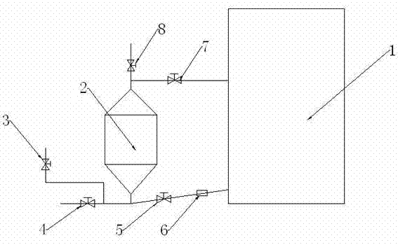
[0042] The activated sludge reaction system described in this embodiment is as figure 1 shown, including:

[0043] Reactor 1, described reactor is normal pressure reactor, and the top of described reactor 1 communicates with atmosphere, and described reactor is high 50m;

[0044] Replacement tank 2, the height of described replacement tank 2 is 6m; Described replacement tank 2 is arranged near the bottom of described reactor 1, is in horizontal position substantially with the high-pressure zone of described reactor 1;

[0045] In communication with the replacement tank 2, an inlet valve 4 for sending untreated sewage into the replacement tank 2 and an outlet valve 3 for releasing the liquid in the replacement tank 2 are provided. The top is provided with an exhaust valve 8; in order to avoid dead ends, the replacement tank 2 in this embodiment includes a cylindrical cylinder and conical cylinders respectively connected to the two bottom surfaces of the cylindrical cylinder. ...

Embodiment 2

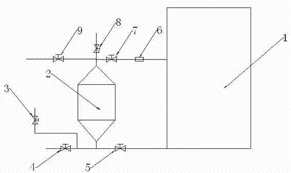
[0053] The activated sludge reaction system described in this embodiment is as figure 2 shown, including:

[0054] Reactor 1, the reactor is a normal pressure reactor, the top of the reactor 1 communicates with the atmosphere, and the reactor is 100m high;

[0055] Replacement tank 2, the height of described replacement tank 2 is lower than the height of described reactor 1, and the height of described replacement tank 2 is 8m; The high pressure zone of the reactor 1 is in a horizontal position;

[0056] In communication with the replacement tank 2, an inlet valve 4 for sending untreated sewage into the replacement tank 2 and an outlet valve 3 for releasing the liquid in the replacement tank 2 are provided. The top is provided with an exhaust valve 8 and a mud discharge valve 9; the replacement tank 2 in this embodiment includes a cylindrical shell and a conical shell respectively connected to the two bottom surfaces of the cylindrical shell. The two tapered barrels gradua...

Embodiment 3

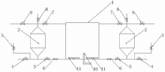
[0065] The activated sludge reaction system described in this embodiment is as image 3 shown, including:

[0066] Reactor, the reactor is a high-pressure reactor, the air pressure in the reactor is 1Mpa, and the reactor is 15m high;

[0067] In this embodiment, a reactor 1 is equipped with two sets of replacement devices, and each replacement device includes:

[0068] Replacement tank 2, the height of the replacement tank 2 is 15m; the replacement tank 2 and the reactor are basically in a horizontal position, and the replacement tank 2 is connected with a water inlet valve 4 and a water outlet valve 3. The top of the replacement tank 2 is provided with an exhaust valve 8 and a mud discharge valve 9; the replacement tank 2 in this embodiment includes a cylindrical shell and conical cones respectively connected to the two bottom surfaces of the cylindrical shell. The barrel body, the two tapered barrel bodies shrink gradually along the direction away from the cylindrical barr...


PUM

PropertyMeasurementUnit
heightaaaaaaaaaa
heightaaaaaaaaaa

Abstract

The invention relates to an activated sludge reaction system which comprises a reactor and a replacement device connected with the reactor, wherein the replacement device comprises a replacement tank which is basically parallel to the high pressure area of the reactor, and a water inlet valve and a water outlet valve which are communicated with the replacement tank; the replacement device also comprises an exhaust valve arranged on the top of the replacement tank; a first circulating pipeline and a second circulating pipeline are also arranged; the replacement tank is communicated with the reactor respectively by virtue of the first circulating pipeline and the second circulating pipeline; the first circulating pipeline is provided with a first circulating water valve, and the second circulating pipeline is provided with a second circulating water valve; and the first circulating pipeline or the second circulating pipeline is provided with a flow push device. The activated sludge reaction system can be used for replacing the inflow water and outflow water of the rector by the replacement device, so that the total energy consumption is lower than the water inlet energy consumption of a reactor barrel.

Description

technical field [0001] The invention relates to the field of wastewater treatment, in particular to an activated sludge reaction system. Background technique [0002] Activated sludge method is an aerobic biological treatment method that uses microbial flocs to treat wastewater. The principle of activated sludge method is to use aerobic microorganisms in water to absorb and consume organic matter under aerobic conditions, thereby removing organic pollutants. . The activated sludge treatment system is basically composed of an aeration tank, an aeration device, a sedimentation tank and sludge return equipment. Under the aeration of the device, the sewage is in full contact with the activated sludge, and the organic matter in the wastewater is adsorbed by the activated sludge, and is metabolized and decomposed by the microbial population in the activated sludge, thereby reducing the content of organic matter in the water. [0003] The aeration tank in the activated sludge met...

Claims


Application Information

Patent Timeline
Patent Type & Authority Applications(China)
IPC IPC(8): C02F3/12
CPCY02W10/10
Inventor 冯秀娟
Owner SHENZHEN DEWEI INTELLIGENT MFG TECH CO LTD
Why Eureka
Try Eureka