
Tumble-flow accelerating combustion chamber

A combustion chamber and tumble flow technology, which is applied to combustion engines, variable displacement engines, reciprocating piston engines, etc., can solve the problem that the performance of the piston tops 22 and 24 cannot be optimized.

Inactive Publication Date: 2013-01-30
ECOMOTORS INTL
View PDF7 Cites 11 Cited by
  • Summary
  • Abstract
  • Description
  • Claims
  • Application Information

AI Technical Summary

Problems solved by technology

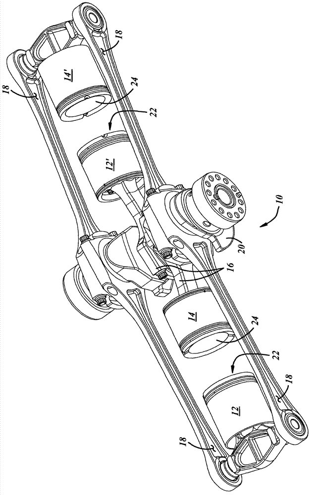
figure 1 The piston tops 22 and 24 in the

Method used


Image

  • Tumble-flow accelerating combustion chamber
  • Tumble-flow accelerating combustion chamber
  • Tumble-flow accelerating combustion chamber

Examples


Embodiment Construction

[0022] As is known to those of ordinary skill in the art, various features of an embodiment described and illustrated with reference to any one figure may be combined with features shown in one or more other figures to form alternative embodiments not explicitly illustrated or described . Combinations of features shown provide representative implementations for typical applications. However, various combinations and modifications of the features consistent with the teachings of the present invention may be desired for particular applications or practices. One of ordinary skill in the art would recognize similar applications or practices whether or not explicitly described or illustrated.

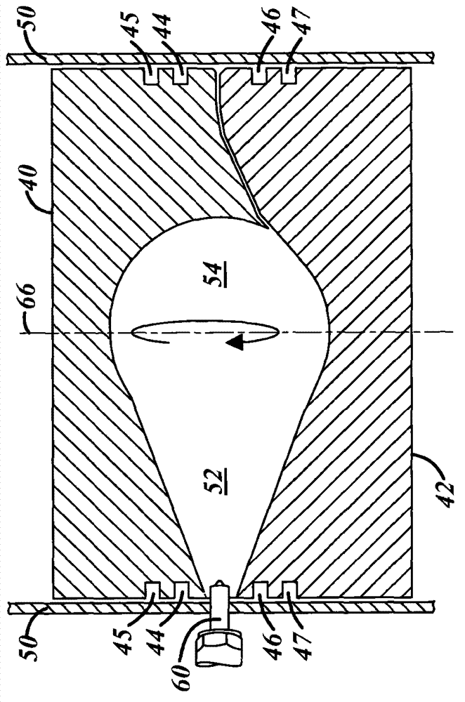
[0023] figure 2 A cross-section of a portion of an OPOC engine illustrating a combustion chamber according to an embodiment of the invention is shown in . A portion of the intake piston 40 and a portion of the exhaust piston 42 are shown in their closest positions. Piston 40 has grooves...


PUM


Abstract

The invention relates to a tumble-flow accelerating combustion chamber. The combustion chamber in an opposed-piston, internal-combustion engine is disclosed in which the pistons tops are designed so that when they approach each other, they induce a tumble flow in one or two spherical spaces defined in the piston tops. The combustion chamber further includes injectors side mounted in the cylinder wall. In one embodiment, the tumble flows in the two spaces are in the same direction and in another embodiment, in opposite directions. In yet another embodiment, there is only one injector and one hemisphere in which a tumble flow is induced.

Description

[0001] Cross References to Related Applications [0002] This application claims priority to US Provisional Patent Application 61 / 508,151, filed July 15, 2011, and US Provisional Patent Application 61 / 523,360, filed August 14, 2011. technical field [0003] The invention relates to combustion chamber shape and injector orientation in internal combustion engines. Background technique [0004] Thermal efficiency and engine emissions from an internal combustion engine are determined by many factors including, for example, combustion chamber shape, fuel injection nozzles, fuel injection pressure. Much is known and studied in a typical diesel engine combustor. However, in unconventional engines, it is less known how combustion chamber shape and fuel injection characteristics may provide the desired performance. [0005] This unconventional engine (opposed-piston, opposed-cylinder (OPPC) engine10) was figure 1 Expressed neutrally. An intake piston 12 and an exhaust piston 14 r...

Claims


Application Information

Patent Timeline
Patent Type & Authority Applications(China)
IPC IPC(8): F02B75/24F02B23/00F02F3/28
CPCF02B75/24F02B2023/0615F02B23/066F02B75/28F02B23/0633F02B75/282F02B23/06F02B23/00F02F3/28F01B7/08F02B23/0678F02B23/0687F02B23/069
Inventor P·P·霍夫鲍尔A·N·图希尼安
Owner ECOMOTORS INTL
Learn More