Electromagnetic suspension

A technology of electromagnetic and suspension devices, applied in the direction of suspensions, elastic suspensions, electromechanical devices, etc., can solve problems such as unrecorded wiring

Active Publication Date: 2013-01-30
HITACHI ASTEMO LTD
View PDF11 Cites 11 Cited by
  • Summary
  • Abstract
  • Description
  • Claims
  • Application Information

AI Technical Summary

Problems solved by technology

In this case, it is required to ensure the reliability and handleability of the wiring with respect to the armature. However, in the above-mentioned three patent publications, all describe a cylindrical magnet (permanent magnet) in which the armature is arranged on the outer periphery. Linear motors do not describe the wiring of cylindrical linear motors in which magnets (permanent magnets) are arranged on the outer circumference of the armature

Method used


Image

  • Electromagnetic suspension
  • Electromagnetic suspension
  • Electromagnetic suspension

Examples


Embodiment Construction

[0013] One embodiment of the present invention will be described based on the drawings.

[0014] refer to figure 1 and figure 2 A first embodiment of the present invention will be described. It should be noted that the upper (upper side) and lower (lower side) in the following description are figure 1 In the vertical observation from the front (orthogonal view), the reference signs are the upper (upper side) and lower (lower side) in the positive case.

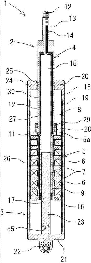
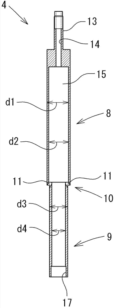
[0015] figure 1 It is an axial sectional view showing the overall structure of a cylindrical linear motor used in the electromagnetic suspension device 1 of the first embodiment. As shown in the figure, the linear motor is composed of a stator 2 attached to a sprung member of a vehicle and a rotor 3 attached to an unsprung member of a vehicle.

[0016] The stator 2 includes a cylindrical first piston rod 4 and an armature 5 formed on the lower side (the other end side) of the first piston rod 4 . The armature 5 has: a p...


PUM


Abstract

An electromagnetic suspension system uses a linear motor having coils (6) disposed around the outer periphery of a stator (2) and permanent magnets (19) disposed along the inner periphery of a mover (3). Wiring (12) is routed through a gap (27) between a first rod (4) and a second rod (23). Thus, contact between the wiring (12) and the second rod (23) is avoided, and the wiring (12) is protected. Consequently, it is possible to ensure reliability for the electric system of the electromagnetic suspension system.

Description

technical field [0001] The present invention relates to an electromagnetic suspension using a linear motor. Background technique [0002] It is well known that, for example, an electromagnetic suspension described in Japanese Patent No. 4538771 is disclosed. Therein, in this electromagnetic suspension, a sliding support structure of a long member and an outer cylinder member is disclosed in which the vibration suppression performance is improved by reducing the gap (gap) between the permanent magnet of the linear motor and the outer cylinder member. [0003] In addition, Japanese Patent Application Laid-Open No. 2005-20903 discloses a winding arrangement for a moving magnet type linear motor in which workability of wiring is improved by using a winding arrangement member of a non-conductive material with an upper opening formed in a tubular shape. wire parts. [0004] Furthermore, Japanese Patent Application Laid-Open No. 2007-321863 discloses a damping force adjustable da...

Claims


Application Information

Patent Timeline
Patent Type & Authority Applications(China)
IPC IPC(8): F16F15/03B60G13/00
CPCF16F15/03H02K7/003H02K41/031H02K2213/03H02K7/08H02K3/46B60G11/00B60G13/00B60G2202/16B60G2202/20B60G2202/44Y10T29/49009F16F9/50B60G17/015H02K41/02
Inventor 李友行内海典之吉仓博史
Owner HITACHI ASTEMO LTD
Why Eureka
Try Eureka