Heat supplying function and air conditioning function switching device of waterway switching heat pump system

A technology of function switching and heat pump system, which is applied in the field of heating and air conditioning function switching device of water circuit switching heat pump system, can solve the problems of undetectable leakage, difficult cleaning, complicated operation, etc., to reduce the difficulty of opening and closing identification, simple operation, Easy-to-use effects

Active Publication Date: 2013-01-30
HARBIN INST OF TECH
View PDF3 Cites 1 Cited by
  • Summary
  • Abstract
  • Description
  • Claims
  • Application Information

AI Technical Summary

Problems solved by technology

[0003] The purpose of the present invention is to solve the existing problems of extremely complicated operation, undetectable leakage, and difficult cleaning of heat pump system heating and air conditioning function switching realized by the opening and closing of the waterway valve group, and to provide a waterway switching heat pump system heating and air conditioning system. Air Conditioning Function Switching Device

Method used


Image

  • Heat supplying function and air conditioning function switching device of waterway switching heat pump system
  • Heat supplying function and air conditioning function switching device of waterway switching heat pump system
  • Heat supplying function and air conditioning function switching device of waterway switching heat pump system

Examples


specific Embodiment approach 1

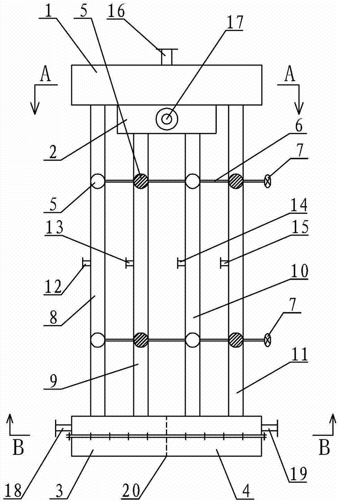
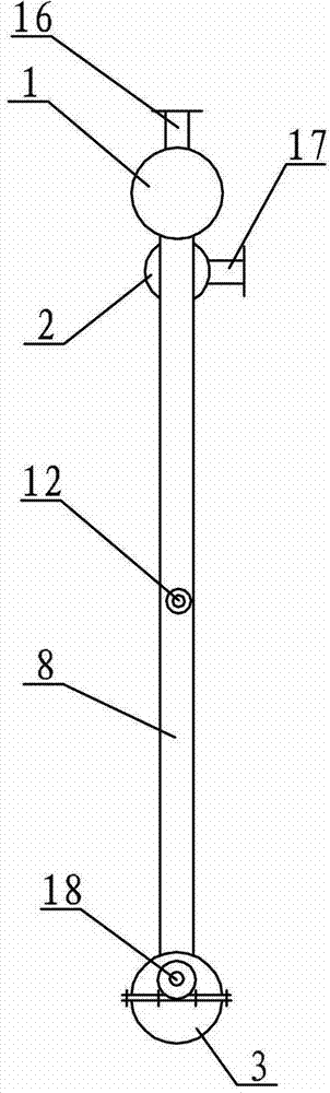
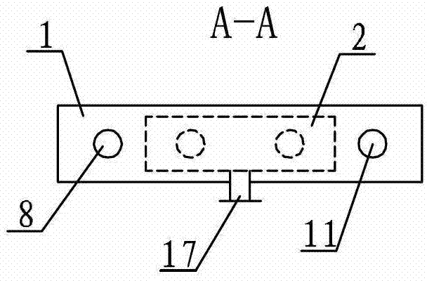
[0010] Specific implementation mode one: combine Figure 1 ~ Figure 4Describe this embodiment, this embodiment includes two function switching devices, each function switching device includes a first water storage tank 1, a second water storage tank 2, a third water storage tank 3, a fourth water storage tank 4, and a first connecting pipe 8 , the second connecting pipe 9, the third connecting pipe 10, the fourth connecting pipe 11, the first drain pipe 12, the second drain pipe 13, the third drain pipe 14, the fourth drain pipe 15, two valve shafts 6, two A hand wheel 7 and eight valves 5, the first water storage tank 1, the second water storage tank 2, the third water storage tank 3 and the fourth water storage tank 4 are respectively provided with a first opening 16, a second opening 17, a first opening 17, and a second opening 17. Three openings 18 and a fourth opening 19, the second water storage tank 2 is arranged below the first water storage tank 1, the first water sto...

specific Embodiment approach 2

[0015] Specific implementation mode two: combination Figure 5 ~ Figure 8 Describe this embodiment, this embodiment includes two function switching devices, each function switching device includes a first water storage tank 1, a second water storage tank 2, a third water storage tank 3, a fourth water storage tank 4, and a first connecting pipe 8 , the second connecting pipe 9, the third connecting pipe 10, the fourth connecting pipe 11, the first drain pipe 12, the second drain pipe 13, the third drain pipe 14, the fourth drain pipe 15, two valve shafts 6, two A hand wheel 7 and eight valves 5, the first water storage tank 1, the second water storage tank 2, the third water storage tank 3 and the fourth water storage tank 4 are respectively provided with a first opening 16, a second opening 17, a first opening 17, and a second opening 17. Three openings 18 and a fourth opening 19, the second water storage tank 2 is arranged below the first water storage tank 1, the first wate...

specific Embodiment approach 3

[0018] Specific implementation mode three: combination Figure 9 ~ Figure 13Describe this embodiment, this embodiment includes two function switching devices, each function switching device includes a first water storage tank 1, a second water storage tank 2, a third water storage tank 3, a fourth water storage tank 4, and a first connecting pipe 8 , the second connecting pipe 9, the third connecting pipe 10, the fourth connecting pipe 11, the first drain pipe 12, the second drain pipe 13, the third drain pipe 14, the fourth drain pipe 15, four valve shafts 6, four A hand wheel 7 and eight valves 5, the first water storage tank 1, the second water storage tank 2, the third water storage tank 3 and the fourth water storage tank 4 are respectively provided with a first opening 16, a second opening 17, a first opening 17, and a second opening 17. Three openings 18 and a fourth opening 19, the second water storage tank 2 and the first water storage tank 1 are arranged side by side...


PUM


Abstract

The invention discloses a heat supplying function and air conditioning function switching device of a waterway switching heat pump system, relates to a switching device of a heat pump system and aims to solve the problems that when the heat supplying and air conditioning functions of the heat pump system are switched by depending on starting and stopping of the conventional waterway valve group, valves are complexly operated, and leakage cannot be found. According to a scheme 1, a first connection pipe, a second connection pipe, a third connection pipe, and a fourth connection pipe are parallelly arranged on the same plane, operation directions of valves on the first connection pipe and the third connection pipe are the same, operation directions of valves on the second connection pipe and the fourth connection pipe are the same, four valves which are arranged on the upper part and positioned on the same horizontal straight line are respectively connected with one valve shaft; four valves which are arranged on the lower part and positioned on the same horizontal straight line are respectively connected with the other valve shaft; and a hand wheel is arranged at the end of each valve shaft. According to a scheme 3, a first water storage box and a second water storage box are parallelly arranged longitudinally, and a first connection pipe, a second connection pipe, a third connection pipe, and a fourth connection pipe are arranged in a square mode. The heat supplying function and air conditioning function switching device is applied to a water source heat pump system.

Description

technical field [0001] The invention relates to a switching device for a heat pump system, in particular to a switching device for heating and air conditioning functions of a waterway switching heat pump system. Background technique [0002] There are two main forms for the heat pump system to realize the function switching of heating in winter and air conditioning in summer: one is the unit-side switching mode, that is, the function switching is realized by reversing the flow direction of the refrigerant by relying on the four-way reversing valve in the heat pump unit; The other is the waterway switching mode, that is, outside the heat pump unit, relying on different opening and closing combinations of at least eight valves, the function switching is realized by reversing the flow direction of the low-level heat source water and the end circulating water. At present, the waterway switching mode of the heat pump system is more widely used, but the waterway switching mode sti...

Claims


Application Information

Patent Timeline
IPC IPC(8): F25B29/00F25B41/04
Inventor 张承虎李亚平
Owner HARBIN INST OF TECH
Why Eureka
Try Eureka