Automatic cutter detection equipment

An automatic detection and tool technology, applied in measuring/indicating equipment, metal processing equipment, measuring devices, etc., can solve the problems of inaccurate detection and low detection efficiency, and achieve the effect of avoiding inaccurate positioning and improving detection efficiency.

Inactive Publication Date: 2013-01-30
SHENZHEN SHENLAN PRECISION MACHINERY
View PDF3 Cites 16 Cited by
  • Summary
  • Abstract
  • Description
  • Claims
  • Application Information

AI Technical Summary

Problems solved by technology

[0004] The purpose of the present invention is to provide automatic detection equipment for cutting tools, aiming to solve the problems of low detection efficiency and inaccurate detection caused by manual operation of milling cutters in the prior art

Method used


Image

  • Automatic cutter detection equipment
  • Automatic cutter detection equipment
  • Automatic cutter detection equipment

Examples


Embodiment Construction

[0019] In order to make the object, technical solution and advantages of the present invention clearer, the present invention will be further described in detail below in conjunction with the accompanying drawings and embodiments. It should be understood that the specific embodiments described here are only used to explain the present invention, not to limit the present invention.

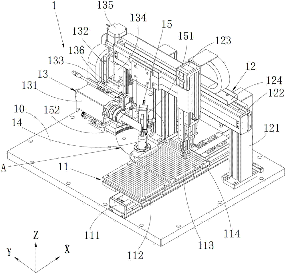
[0020] The invention provides automatic detection equipment for knives, including a control center, and a base, a tray placed on the base and movable along the horizontal direction of the base and used for placing the knives to be tested and the knives that have been tested, A collet seat placed on the base for clamping the tool to be detected and allowing the tool to be detected to rotate with the longitudinal direction as the center of rotation can move along the vertical direction and the longitudinal direction and can align the collet seat The detection mechanism for detecting the tool to be de...


PUM


Abstract

The invention belongs to the technical field of detection equipment and discloses automatic cutter detection equipment which comprises a control center, a base, a feed plate, a chuck seat, a detection mechanism and a grabbing mechanism. The feed plate is arranged on the base, the chuck seat is rotatable and used for clamping a to-be-detected cutter, the detection mechanism is used for detecting the to-be-detected cutter, and the grabbing mechanism is capable of grabbing a cutter in the feed plate and arranged above the base. The chuck seat is arranged between the detection mechanism and the feed plate, and the control center controls operations of the feed plate, the chuck seat, the grabbing mechanism and the detection mechanism. The grabbing mechanism is capable of grabbing the to-be-detected cutter in the feed plate to place the cutter in the rotatable chuck seat under control of the control center, the detection mechanism detects the to-be-detected cutter and is capable of moving vertically and longitudinally, and the grabbing mechanism can further place the detected cutter on the feed plate. The whole operation process is automatic, and accordingly cutter detection efficiency is greatly improved, and accuracy in positioning and detection of cutters are achieved.

Description

technical field [0001] The invention relates to the technical field of detection equipment, in particular to automatic detection equipment for knives. Background technique [0002] A milling cutter is a rotating tool for milling a workpiece, which has one or more teeth. The milling cutter is mainly used on the milling machine to process planes, steps and grooves on the workpiece, or to shape the surface of the workpiece or cut off the workpiece. quantity. Milling cutters are divided into cylindrical milling cutters, face milling cutters, end milling cutters, three-sided milling cutters, angle milling cutters, saw blade milling cutters, T-shaped milling cutters, etc. In this way, the blade angles and geometric shapes on them are also different. Therefore, in the process of manufacturing milling cutters in large quantities, it is necessary to check whether the milling cutters are ground to the preset blade angles and geometric shapes one by one. The blade width, ligament wi...

Claims


Application Information

Patent Timeline
Patent Type & Authority Applications(China)
IPC IPC(8): G01B11/00
CPCB23Q17/00B23Q17/0919
Inventor 郑青焕
Owner SHENZHEN SHENLAN PRECISION MACHINERY
Why Eureka
Try Eureka