Geographic Tracking Method Based on Coincidence of Optical Axis and Inertial Axis

A technology of inertial axis and optical axis, applied in surveying and navigation, control using feedback, measuring devices, etc., can solve the problem that the position of the target bullseye cannot be guaranteed, the target can only appear in the field of view of the camera, and the target cannot be kept continuously. Stable tracking and other issues

Active Publication Date: 2015-08-12
中国兵器工业第二0五研究所
View PDF0 Cites 0 Cited by
  • Summary
  • Abstract
  • Description
  • Claims
  • Application Information

AI Technical Summary

Problems solved by technology

The technical solution provided in the paper does not propose the requirement that the optical axis and the inertial axis of the photoelectric load system need to coincide. Therefore, only relying on the calculation of the space vector angle of the target and inputting it to the servo control unit, the servo control unit adjusts the angle of the stable turntable. Can make the target appear in the field of view of the camera, but cannot guarantee the bull's-eye position of the target in the field of view
Therefore, using the geographic tracking method in the paper alone cannot maintain continuous and stable tracking of the target.

Method used


Image

  • Geographic Tracking Method Based on Coincidence of Optical Axis and Inertial Axis
  • Geographic Tracking Method Based on Coincidence of Optical Axis and Inertial Axis
  • Geographic Tracking Method Based on Coincidence of Optical Axis and Inertial Axis

Examples


Embodiment Construction

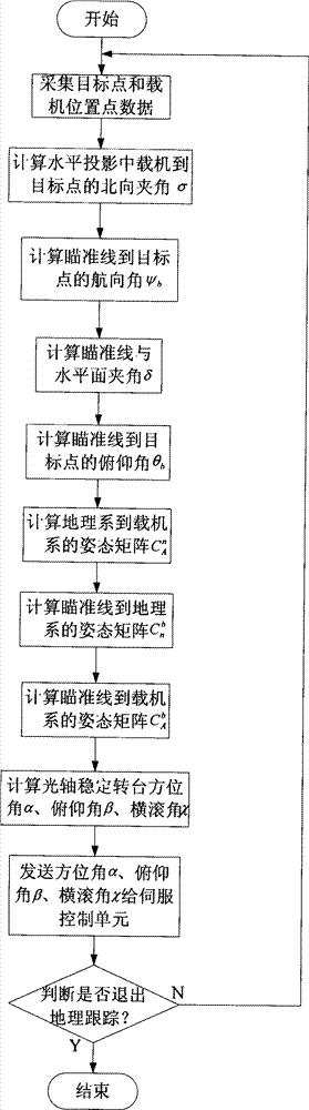
[0058] The present invention will be further described in detail below in conjunction with the accompanying drawings and preferred embodiments.

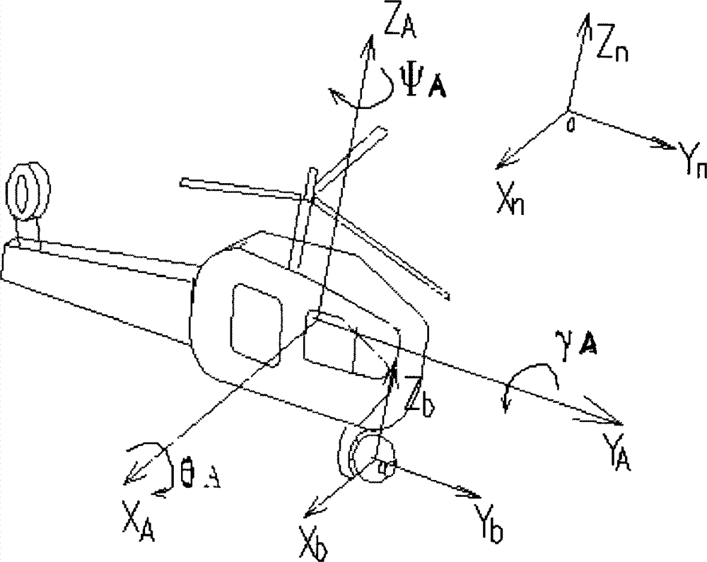
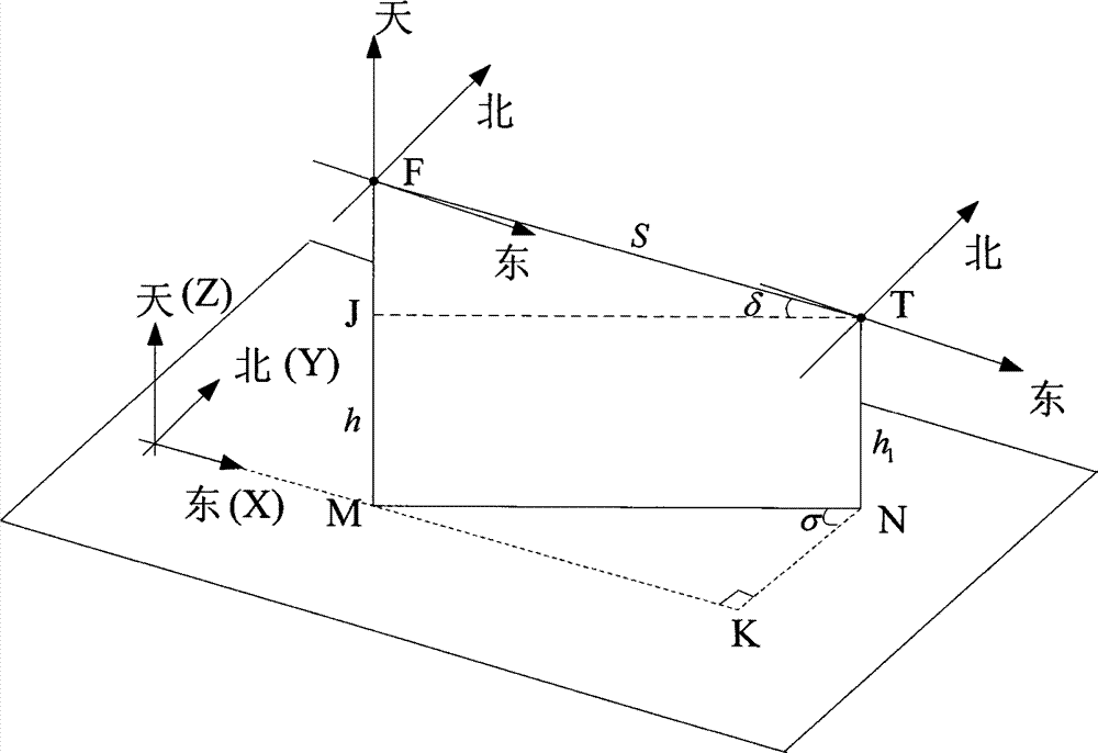
[0059] The preferred embodiment of the geographical tracking method of the present invention is used in an unmanned aerial vehicle photoelectric detection / tracking system for tracking a certain fixed target. The system includes an optical axis stabilized turntable, an inertial navigation unit, a servo control unit, and an information processing unit. Wherein, the optical axis on the optical axis stabilized turntable coincides with the inertial axis of the inertial navigation unit, and the information processing unit includes a computer equipped with a geographic tracking module. This method is realized by the computer in the information processing unit. The parameter flatness e and the major axis radius R of the earth ellipsoid are stored in the hard disk of the computer in advance e . During the flight of the UAV, if the airborne...


PUM


Abstract

The invention discloses an optic axis and inertia axis superposition-based geographic tracking method which comprises the steps of computing the space pose of a carrier aiming line in real time by using a space two-point geometric algorithm according to the positioning data and the self position information of a target, computing the space angle of the aiming line relative to a carrier coordinate system by being combined with the carrier space pose and the space coordinate transformation principle, sending the angle to a servo control unit, and adjusting corresponding space pose of a turntable by the servo control unit so as to complete the geographic tracking to the target. The method is different from the image tracking method in terms of theory, therefore, the method is not influenced by the cloud, the mist and the obstacles; and when being used on aircrafts, the method is capable of avoiding the problem of losing the target due to strenuous vibration or sight shielding, so that the scouting and searching capabilities of the battlefield weapon systems are remarkably improved. The method can also be used for guide devices of various guided missiles, so as to improve the accurate attacking capability to ground targets.

Description

technical field [0001] The invention belongs to the field of photoelectric reconnaissance and target tracking, and mainly relates to a geographical tracking method for a target, in particular to a geographical tracking method based on the coincidence of an optical axis and an inertial axis. Background technique [0002] The photoelectric tracker of a modern weapon system has the functions of target reconnaissance, search and tracking. The current automatic tracking function is divided into three tracking methods: laser, infrared and TV according to the form of the target detector. The basic principles of these three tracking methods are as follows: when the target detector captures the target, the CCD (charge-coupled device) converts the target scene into an electronic image, and then the signal processing unit measures the off-target of the image and automatically outputs the off-target amount. Then the difference taker converts the miss amount into an electrical signal an...

Claims


Application Information

Patent Timeline
Patent Type & Authority Patents(China)
IPC IPC(8): G05D3/12G01C1/00
Inventor 陈颖纪明陈文建张建峰马忠孝唐超李颖娟易科扈宇姝许开銮韩峰张夏疆
Owner 中国兵器工业第二0五研究所
Why Eureka
Try Eureka