Airplane taking-off and landing tracking system and method

A technology for tracking systems, aircraft, applied in the field of computer vision

Inactive Publication Date: 2017-11-24
HARBIN UNIV OF SCI & TECH
View PDF3 Cites 8 Cited by
  • Summary
  • Abstract
  • Description
  • Claims
  • Application Information

AI Technical Summary

Problems solved by technology

[0016] Adapting to the development trend of moving target tracking systems, the present invention discloses an aircraft take-off and landing tracking system and method. The purpose of the invention is to achieve the following goals: preprocessing the collected images, filtering out the noise in the images, and improving the original image data , suppress unnecessary deformation and enhance the features required for image follow-up processing; realize real-time detection and tracking of moving targets, and can continuously and stably track when the posture of the moving target changes or temporarily disappears due to occlusion; Rotate with the movement of the moving target, keep the moving target in the center of the screen

Method used


Image

  • Airplane taking-off and landing tracking system and method
  • Airplane taking-off and landing tracking system and method

Examples


specific Embodiment 1

[0037] This embodiment is an embodiment of the aircraft take-off and landing tracking system.

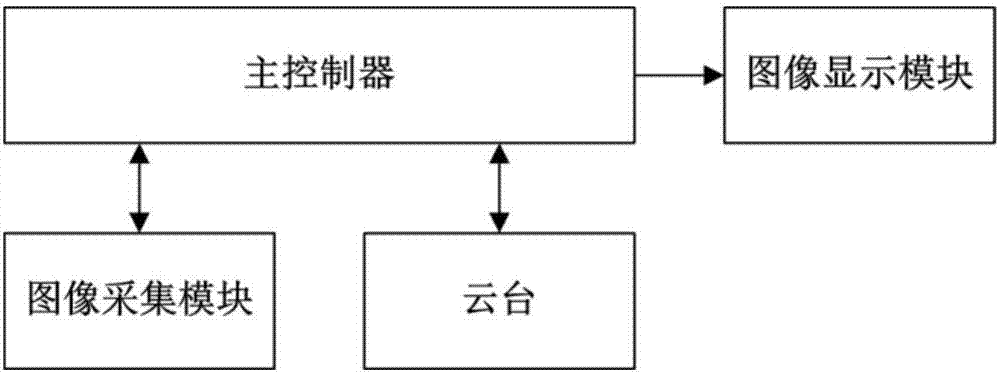
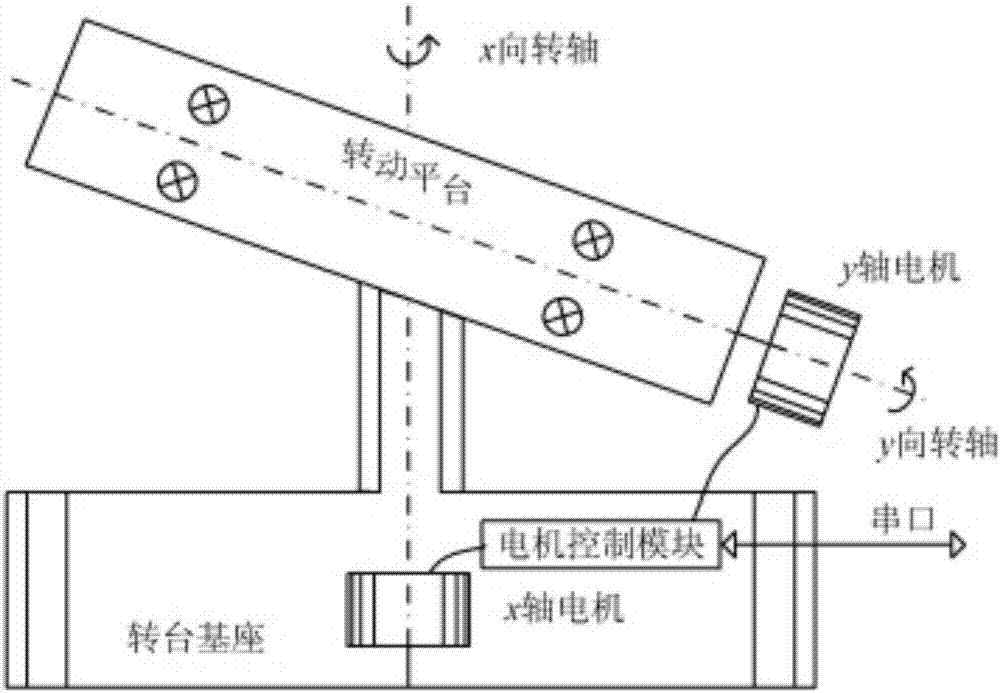
[0038] The aircraft take-off and landing tracking system of this embodiment, the schematic diagram is as figure 1 shown. The aircraft take-off and landing tracking system includes an image acquisition module, an image display module and a cloud platform controlled by a main controller; the image acquisition module collects images through a USB camera, and the image display module utilizes a VGA interface to be connected to a liquid crystal display, and the cloud platform Adjust its own movement so that the camera can follow the moving target.

[0039] in,

[0040] Main controller: S3C2440 chip is used as the core processor, and the "core board + base board" structure is adopted. The core board is 6 layers; the base board is 2 layers, with multiple USB serial ports for various handheld devices, consumer electronics and industrial control Development of equipment; FLASH storage uni...

specific Embodiment 2

[0044] This embodiment is an embodiment of the aircraft take-off and landing tracking method.

[0045] The aircraft take-off and landing tracking method in this embodiment consists of three steps: image preprocessing, image recognition, and moving target tracking.

[0046] Described image preprocessing is made up of image denoising and image edge detection two steps; Described:

[0047] Image denoising, because the median filtering method is not sensitive to the extreme pixel value and produces less blur, it is very suitable for eliminating isolated noise points in the image, so the median filtering method is used to denoise the image; The adjacent area of ​​​​a pixel is operated to determine the value of the output pixel. The pixel and its adjacent area form a set of arrays. The median filter only calculates the median value of this set of numbers and replaces the current pixel value with the median value;

[0048] For image edge detection, the Sobel operator calculates the ...


PUM


Abstract

The invention provides an airplane taking-off and landing tracking system and method, which belong to the technical field of computer vision. The system comprises an image acquisition module, an image display module and a holder that are controlled by a main controller. The image acquisition module acquires images through a USB camera. The image display module is connected to a liquid crystal display screen through a VGA interface. The holder adjusts movements of itself to make the camera move closely along with moving targets. The method consists of three steps: image preprocessing, image identifying, and moving target tracking. Acquired images are pre-processed, noise in the images is filtered, original image data is improved, unnecessary deformation is inhibited, and features that are needed for subsequent processing of the images are improved. The moving targets can be detected and tracked in real time. If the moving targets change in posture or temporarily disappear because of being shielded, the moving targets can be tracked continuously and stably. The holder rotates along with moving of the moving targets, thereby keeping the moving targets always in the middle of a frame.

Description

technical field [0001] The invention relates to an aircraft take-off and landing tracking system and method, which belong to the technical field of computer vision. Background technique [0002] The advent of the information society has made the monitoring system widely used. The original traditional monitoring mode using video recorders and monitors requires manual monitoring of the pictures collected by the camera, which consumes human resources. This method is slowly being adopted by the new generation of computer intelligent video Surveillance replaced. Intelligent video surveillance is a practical direction derived from the field of computer vision. It mainly uses computer vision technology to analyze and process the acquired video signals, so that the system has the ability to respond in time to events that occur in the video. [0003] With the continuous development of the economy, the cargo and passenger volumes of the air transport industry are growing rapidly. Th...

Claims


Application Information

Patent Timeline
IPC IPC(8): G06T7/277G06T7/13G06K9/46H04N7/18
CPCH04N7/18G06T7/13G06T7/277G06T2207/30232G06T2207/10016G06T2207/20032G06V10/462
Inventor 李莉徐志成胡黎昆王贺杨兆鹏
Owner HARBIN UNIV OF SCI & TECH
Why Eureka
Try Eureka