Variable displacement lubricant pump

A lubricant pump and lubricant technology, applied in the field of lubricant pumps, can solve the problems of inappropriate lubricant flow rate, disturbance of balance force, unsuitability for engines, etc.

Active Publication Date: 2013-01-30
PIERBURG PUMP TECH
View PDF6 Cites 12 Cited by
  • Summary
  • Abstract
  • Description
  • Claims
  • Application Information

AI Technical Summary

Problems solved by technology

This maximum compression of the lubricant leads to high local pressure peaks, especially at high speeds and when the control ring is positioned at a high pumped volume, causing a temporarily disturbs the balance of
As a result, the lubricant flow rate will be temporarily inappropriate for the requirements of the engine

Method used


Image

  • Variable displacement lubricant pump

Examples


Embodiment Construction

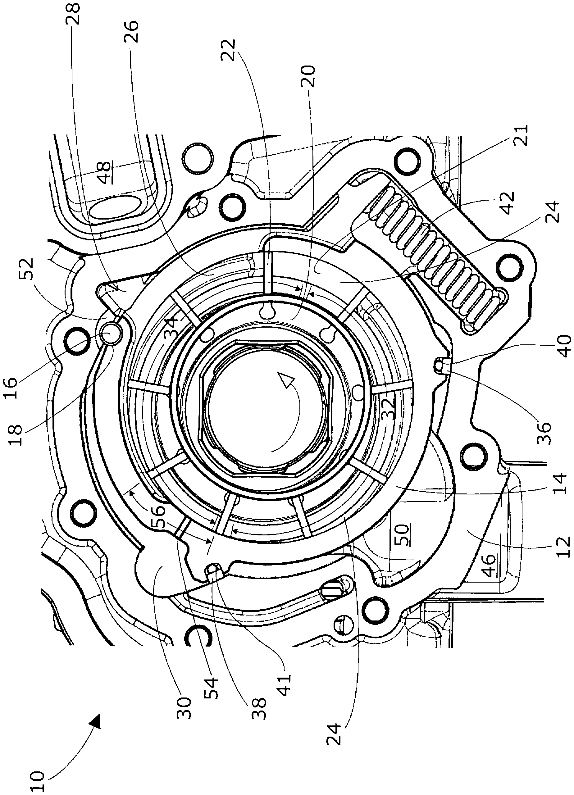
[0017] exist figure 1 In , a variable displacement lubricant pump 10 for an internal combustion engine is shown. The lubricant pump 10 is adapted to supply lubricant to an internal combustion engine, more specifically, to supply lubricant to an internal combustion engine with a lubricant discharge pressure which should not be proportionally dependent on the rotational speed of the pump.

[0018] The variable displacement lubricant pump 10 comprises a metal housing 12 in which a displaceable control ring 14 is arranged axially between two side walls (not shown). The control ring 14 has a pivot 16 about which the control ring 14 pivots such that the control ring 14 is displaced between low and high pumped volume directions. The pivot 16 is realized by a fulcrum pin 18 .

[0019] The metal housing 12 contains a pump rotor 20 having a number of radially slidable vanes 22 whereby the slidable vanes 22 rotate inside a displaceable control ring 14 . The control ring 14 encloses a ...


PUM


Abstract

The present invention refers to a variable displacement lubricant pump (10) for providing pressurized lubricant for an internal combustion engine. The mechanical pump (10) comprises a pump rotor (20) with radially siidable vanes (22) rotating in a shiftable control ring (14), whereby the control ring (14) envelopes numerous pump chambers (24). The pump chambers (24) rotate through a charge and a discharge zone (32, 34) inside the control ring (14). Further, the pump (10) comprises a pretensioning element (42) which is pushing the control ring (14) to a high pumping volume direction. A first control chamber (28) is pushing the control ring (14) to a low pumping volume direction, and a second control chamber (30) is pushing the control ring (14) to a high pumping volume direction if the lubricant is pressurized. The pump (10) also comprises a pump outlet (48) which is connected to the first control chamber (28). Both control chambers, i.e. the first and the second control chamber (28, 30), are connected to each other via a throttle valve (52). Both control chambers (28, 30) can have a different circumferential extend around the control ring (14), so that the effective surfaces of the two control chambers (28, 30) and the respective moment arms are different. Both control chambers (28, 30) act against each other, i.e. act in different pumping volume directions. The control ring (14) of the pump (10) is provided with a pressure relief valve (54) which connects the discharge zone (34) to the second control chamber (30).

Description

technical field [0001] The present invention relates to a variable displacement lubricant pump for supplying pressurized lubricant to an internal combustion engine. Background technique [0002] A mechanical pump comprises a pump rotor with radially slidable vanes rotating in a displaceable control ring whereby said control ring encloses a number of pump chambers. The movement of the control ring does not have to be a linear movement, but can also be a pivotal movement. The pump chamber rotates through the charge and discharge regions inside the control ring. Furthermore, the pump comprises a pretensioning element which pushes the control ring in the direction of a high pumped volume. If the lubricant is pressurized, the first control chamber pushes the control ring in the direction of low pumping volume and the second control chamber pushes the control ring in the direction of high pumping volume. The pump also includes a pump outlet connected to the first control chambe...

Claims


Application Information

Patent Timeline
Patent Type & Authority Applications(China)
IPC IPC(8): F04C2/344F04C15/00F04C14/24F04C14/22
CPCF04C14/24F04C14/226F04C15/0049F04C2/3441
Inventor M.加斯帕里尼S.菲奥里尼M.拉泽里尼R.斯考西尼
Owner PIERBURG PUMP TECH
Why Eureka
Try Eureka