Lubricating oil vane pump

A technology of lubricating oil and vane pump, which is applied in the direction of pressure lubrication, pressure lubricant, and engine lubrication of lubricating pumps, and can solve problems such as reducing the efficiency of lubricating oil vane pumps.

Inactive Publication Date: 2017-08-04
PIERBURG PUMP TECH
View PDF5 Cites 2 Cited by
  • Summary
  • Abstract
  • Description
  • Claims
  • Application Information

AI Technical Summary

Problems solved by technology

This measure reduces the efficiency of the lubricating oil vane pump

Method used


Image

  • Lubricating oil vane pump
  • Lubricating oil vane pump
  • Lubricating oil vane pump

Examples


Embodiment Construction

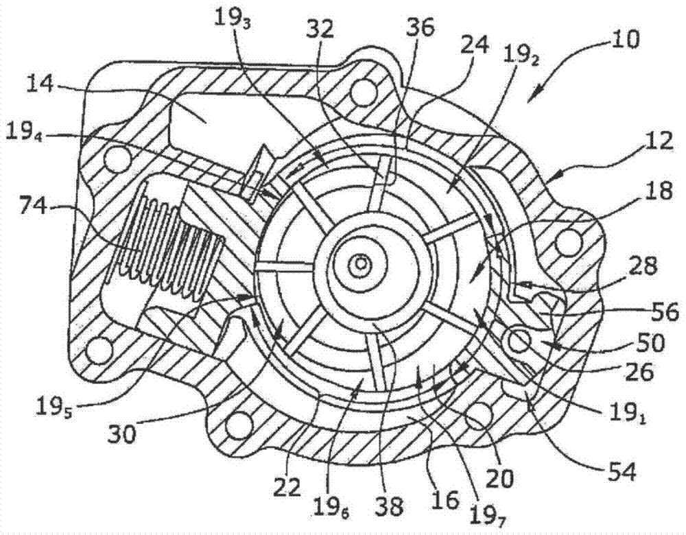
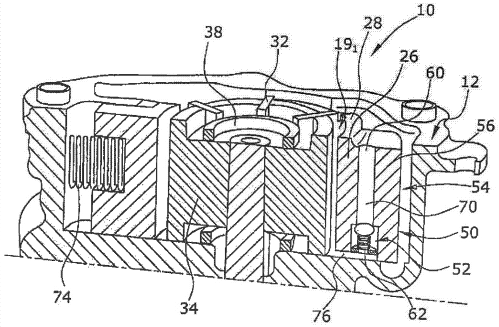
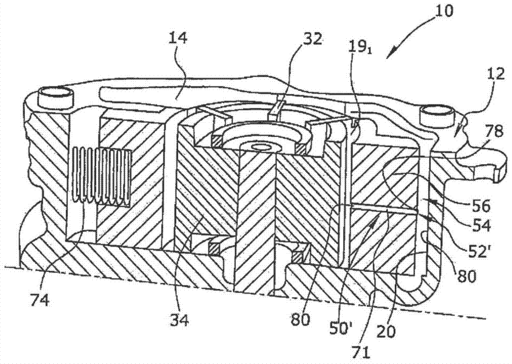
[0027] The drawing shows a lube oil vane pump 10 as part of a pump system for supplying pressurized lube oil to an internal combustion engine. The lubricating oil vane pump 10 pumps lubricating oil with pump outlet pressure to the internal combustion engine and is driven by the engine.

[0028] The lubricating oil vane pump 10 includes a pump housing 12 having a pump inlet chamber 16 and a pump outlet chamber 14 , wherein the housing 12 also includes two chamber side walls 20 covering the pump chamber 18 . The pump housing 12 also defines a pump inlet chamber 16 for drawing oil from the oil tank and a pump outlet chamber 14 for supplying oil at pump outlet pressure to the engine. The pump chamber 18 is divided in the circumferential direction into a filling region 22 connected to the pump inlet chamber 16 , a discharge region 24 connected to the pump outlet chamber 14 and an intermediate region 26 between the filling region 22 and the discharge region 24 .

[0029] In the pum...


PUM


Abstract

The invention relates to a lubricating oil vane pump (10) for supplying pressurized lubricating oil to an internal combustion engine. The lube oil vane pump (10) has a pump housing (12) and a pump rotor (30), wherein the pump rotor (30) has radially slidable vanes (32) rotating in a displaceable control ring (28), The displaceable control ring encloses a pump chamber (18) having a plurality of rotating pump compartments (191-197) rotating from a fill region (22) to a discharge region (24). The pre-tensioning element (74) pushes the control ring (28) in the direction of high pumping volume. High lube oil pressure in the control chamber (54) causes the control ring (28) to move against the pretensioning element (74) in the direction of low pumping volume. The pump out oil chamber (14) is fluidly connected to the control chamber (54). The control loop (28) has pressure relief valves (52, 52') which are integrated into the control loop (28) and connect the control chamber (54) to the filling area (22) and discharge area ( 24) to connect or disconnect the pump compartment (191) between.

Description

technical field [0001] This invention relates to mechanical variable lube vane pumps for supplying pressurized lube oil to internal combustion engines. Background technique [0002] Mechanical lube oil vane pumps are usually positive displacement pumps driven by the engine. Lube oil vane pumps have a pump rotor body that houses radially slidable vanes that rotate within a displaceable control ring. The slidable vanes, rotor body and control ring wall define a plurality of rotating pump compartments that rotate within the pump chamber. The pump chamber is divided into a filling area with an oil inlet, a discharge area with an oil outlet, and an intermediate area between the filling area and the discharge area. Seen in the direction of rotation, the intermediate area is arranged between the filling area and the discharge area. The pump compartment rotates inside the control ring from the filling area through the intermediate area to the discharge area. The pump includes a ...

Claims


Application Information

Patent Timeline
Patent Type & Authority Patents(China)
IPC IPC(8): F04C14/22F04C14/10F04C2/344
CPCF04C2/3442F04C14/10F04C14/22F04C2210/206F01M1/02F01M2001/0238F04C2/3448F04C13/001F04C14/24F04C15/008F04C15/06
Inventor 贾科莫·阿梅尼奥尼古拉·诺维马西米利亚诺·拉泽里尼
Owner PIERBURG PUMP TECH
Why Eureka
Try Eureka