
Speed change device for revolving mop

A technology of rotating mop and speed change device, which is applied in the direction of cleaning carpets, floors, cleaning equipment, etc. It can solve the problems of increased manufacturing cost, complex structure, and low utilization rate, and achieves convenient operation and use, simple and compact structure, and long service life. Effect

Inactive Publication Date: 2013-02-06
浙江万德利工贸有限公司
View PDF6 Cites 13 Cited by
  • Summary
  • Abstract
  • Description
  • Claims
  • Application Information

AI Technical Summary

Problems solved by technology

Although these devices have solved the particularly laborious problem of hand-driven washing, when this device is installed on the mop bucket driven by feet, the lever stroke of the foot-driven itself is relatively short. When stepping on the drive, the rotation speed of the 360° rotating mop will become slower, so that the mop cannot be fully cleaned
If the washing drive shaft is accelerated before deceleration, and then combined with the manual deceleration mechanism, the purpose of saving labor and fully washing can be achieved, but this will increase the complexity of the mechanism and increase the manufacturing cost.
It can be seen that the existing deceleration mechanism and acceleration mechanism are independent of each other, and the utilization rate in the conversion process of useful work is very low, and the structure is complex and the stability is relatively poor.
For this reason, some manufacturers and people of insight have developed and developed speed change devices that integrate acceleration and deceleration mechanisms, but no satisfactory products have come out on the market so far.

Method used


Image

  • Speed change device for revolving mop
  • Speed change device for revolving mop

Examples


Embodiment Construction

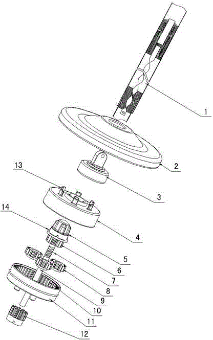
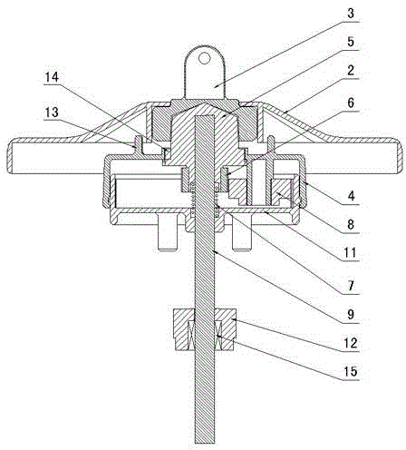
[0017] figure 1 and figure 2 Shown, for the present invention creates the specific embodiment of a kind of rotating mop transmission device, it comprises planetary gear housing 4, cleaning joint 5, driving gear 6, planetary gear set 8, power transmission shaft 9, fixed seat 11, described The fixed seat 11 is fixed on the cleaning bucket, the transmission shaft 9 is fixedly connected with the cleaning connector 5 and is rotatably arranged on the fixed seat 11, and the planetary wheel housing 4 is rotatably covered on the fixed seat 11 to form a closed space. The driving gear 6 and the planetary gear set 8 are installed in the closed space, and the cleaning connector 5 is provided with a transmission disc 14 meshing with the center hole of the planetary gear housing 4, and the head of the cleaning connector 5 protrudes from the planetary gear housing 4. The driving gear 6 is set on the cleaning connector 5 or the transmission shaft 9, the planetary gear set 8 is rotatably set ...


PUM


Abstract

The invention discloses a speed change device for a revolving mop, which comprises a planetary wheel housing (4), a cleaning connector (5), a driving gear (6), a planetary gear set (8), a transmission shaft (9) and a fixing seat (11), wherein the fixing seat (11) is fixed on a cleaning barrel; the transmission shaft (9) is arranged on the fixing seat (11) rotationally after the transmission shaft (9) is fixedly connected with the cleaning connector (5); the fixing seat (11) is covered with the planetary wheel housing (4) rotationally; a transmission disc (14) is arranged on the cleaning connector (5) and meshed with a center hole of the planetary wheel housing (4); the driving gear (6) is arranged on the cleaning connector (5); the planetary gear set (8) is arranged in the planetary wheel housing (4) rotationally; an inner gear ring (10) is arranged on the fixing seat (11); an inner ring of the planetary gear set (8) is meshed with the driving gear (6); and an outer ring of the planetary gear set (8) is meshed with the inner gear ring (10) of the fixing seat (11). With the adoption of the structure, the device has the characteristics of simple and reasonable structure, facilitation of operation and use, good washing effect, long service life and the like.

Description

technical field [0001] The invention relates to a rotary mop dehydration and washing device, in particular to a rotary mop speed change device that provides different rotation speeds according to different driving modes. Background technique [0002] The mop ranges from a simple hand-twist mop to a 360° rotating mop, from a simple foot-driven 360° dehydration bucket to a foot-driven mop bucket for dehydration and washing, to a hand-driven mop bucket for dehydration and washing, and then to both The dual-purpose bucket for dehydration and washing, which can be driven by both feet and hand pressure, has undergone many technical innovations in the field of mop cleaning in just a few years. However, many new problems have also been created in the process, especially on the washing device. As we all know, the resistance of the mop is relatively large when it is rotated and washed in water, especially when it is driven by hand pressure. Therefore, a deceleration device for hand ...

Claims


Application Information

Patent Timeline
IPC IPC(8): A47L13/50
Inventor 黄雪松
Owner 浙江万德利工贸有限公司
Learn More