
Machine tool for machining jaws of bench vices

A technology for processing machine tools and bench vises, which is applied to metal processing machinery parts, metal processing equipment, milling machine equipment, etc., can solve problems such as increased manufacturing costs, large processing errors, and affecting the bite performance of bench vises clamping workpieces, etc., to achieve The effect of improving occlusal performance and avoiding cumulative errors

Inactive Publication Date: 2015-01-21
ZHANGJIAGANG YUCHENG MASCH C0 LTD
View PDF6 Cites 0 Cited by
  • Summary
  • Abstract
  • Description
  • Claims
  • Application Information

AI Technical Summary

Problems solved by technology

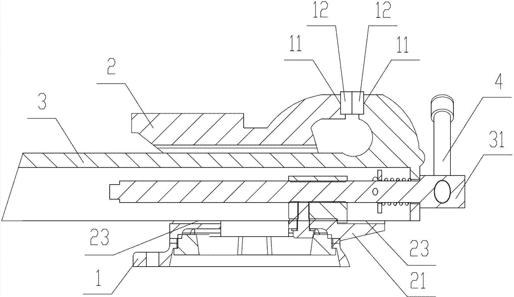
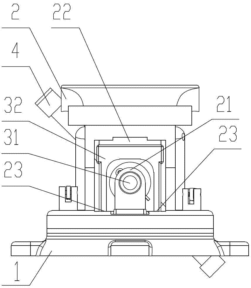
In the prior art, the processing of the bench vise is to process the fixed vise body 2 and the movable vise body 3 respectively through ordinary milling machines or lathes, and then assemble all parts after processing. Due to the accumulation of clamping and machining errors, the The parallelism error between a pair of jaw mounting grooves 11 is relatively large, which affects the bite performance of the bench vise when clamping the workpiece, and ultimately affects the accuracy of the parts processed on the bench vise; in addition, because the various parts of the bench vise are not For regular parts, when the fixed clamp body 2 and the movable clamp body 3 are processed separately, the fixed clamp body 2 and the movable clamp body 3 need to be clamped twice. Not only is the process complicated, the processing error is large, and two sets of fixed molds need to be designed. increase manufacturing cost

Method used


Image

  • Machine tool for machining jaws of bench vices
  • Machine tool for machining jaws of bench vices
  • Machine tool for machining jaws of bench vices

Examples


Embodiment Construction

[0026] The present invention will be further described below in conjunction with the accompanying drawings and specific embodiments (the horizontal direction described in this specification refers to the attached image 3 The left-right direction in this manual refers to the vertical direction in this manual. image 3 In the direction perpendicular to the paper surface inward or outward, the "left" in this manual is the same as the attached figure 1 The left side in the middle is the same, and the "right side" is the same as the attached figure 1 same as the right side in ):

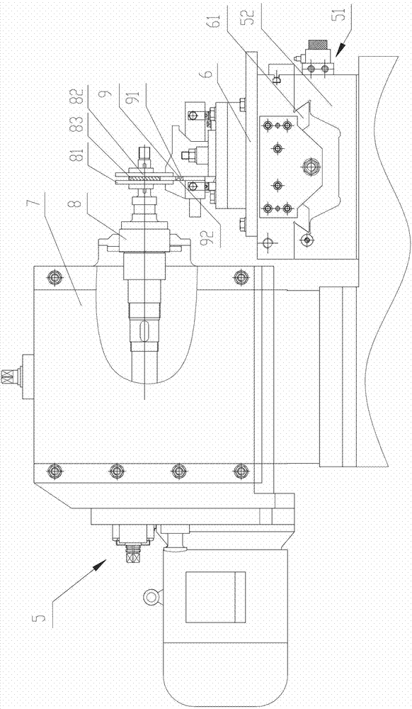
[0027] attached image 3 It is the front view of the bench vise jaw processing machine tool of the present invention, the processing machine tool includes a bed 5, a fixed mounting seat 6 for fixing the bench vise base 1, and a driving fixed mounting seat movably arranged on the bed 5 along the longitudinal direction 6 a moving feed mechanism 51, a column 7 provided on the bed 5, and a spindle 8 provi...


PUM


Abstract

The invention relates to a machine tool for machining jaws of bench vices. The machine tool for machining jaws of bench vices comprises a tool body, a fixed installing seat, a feed mechanism, a stand column and a main shaft, wherein a cushion block is tightly clamped between a fixed vice body and a movable vice body, two end faces of the cushion block, respectively tightly pressed against the jaw end face of the fixed vice body and the jaw end face of the movable vice body, are parallel to each other, one end part of the main shaft can be fixed on the stand column in a rotating way, a first end-face milling tool, a second end-face milling tool and a cushion sleeve are coaxially fixed at the other end part of the main shaft, the second end-face milling tool is parallel to the first end-face milling tool, and the cushion sleeve is arranged between the first end-face milling tool and the second end-face milling tool. According to the invention, when a jaw of a bench vice is machined, the machining of jaw installing grooves is performed in the last step of bench vice machining, and two jaw installing grooves are completely machined once through a pair of parallel end-face milling tools, so that cumulative errors are avoided, and the parallelism of a pair of installing grooves is precisely controlled more easily, thereby improving the occlusion performance of bench vices in the process of clamping workpieces.

Description

technical field [0001] The invention relates to a processing machine tool, in particular to a processing machine tool specially used for processing jaws of bench vices. Background technique [0002] attached figure 1 , 2 Shown is a schematic structural diagram of a bench vise, which includes a base 1, a fixed tong body 2 located on the base 1, a movable tong body 3 that partially passes through the fixed tong body 2, and is respectively fixed on the fixed tong body 2 and the movable tong body 3 steel jaws 12, the base 1 is fastened on the desktop or console by bolts, a screw nut 21 is provided on the fixed clamp body 2, and a screw nut 21 is provided on the movable clamp body 3 to cooperate with the screw nut 21. The screw rod 31 and the moving guide rail 32 located at the right end of the movable tong body 3 have a left and right through groove 22 inside the fixed tong body 2, and the bottom of the through groove 22 is provided with a supporting guide rail 23 that matches...

Claims


Application Information

Patent Timeline
Patent Type & Authority Patents(China)
IPC IPC(8): B23C3/00B23Q1/01B23Q3/06B23Q5/26
Inventor 张玉飞夏小帅陈国昌朱勇黄飞丁绍峰顾玉香
Owner ZHANGJIAGANG YUCHENG MASCH C0 LTD
Learn More