
Apparatus for Welding Continuous Strips Wound on a Support Ring

A technology for supporting rings and strips, applied in the field of strip devices, can solve problems such as poor welding, loss of compactness of seals, and increase in size.

Inactive Publication Date: 2013-02-06
GSKET
View PDF3 Cites 4 Cited by
  • Summary
  • Abstract
  • Description
  • Claims
  • Application Information

AI Technical Summary

Problems solved by technology

[0005] Although fulfilling their function, these machines have several disadvantages for these reasons: they have no means for holding the seal in a direction perpendicular to the axis of rotation of the seal, resulting in a lack of planarity in the formed seal, This also gives rise to imperfections in the final weld, which is made worse by the fact that the welding is performed by the respective components in the radial direction of the screw itself in a circumferential position of the screw away from the position of the pressing component
In addition to the increase in size caused by the double device and the power supply and control for synchronous operation of the two components, in this case, the above-mentioned drawbacks are caused by the fact that the welding is carried out in a different area than the pressing area
[0007] JP8-226544 describes a common welding assembly that acts on the metal strip at the start and end of welding, but does not describe the position and interaction of the pressing assembly
[0008] Moreover, all these solutions of the prior art have the disadvantage that by welding at a position different from that of the pressing assembly, the steel strip will react elastically as it is free along the part between the pressing point and the welding point, As a result, the seal loses its compactness in the radial direction

Method used


Image

  • Apparatus for Welding Continuous Strips Wound on a Support Ring
  • Apparatus for Welding Continuous Strips Wound on a Support Ring
  • Apparatus for Welding Continuous Strips Wound on a Support Ring

Examples


Embodiment Construction

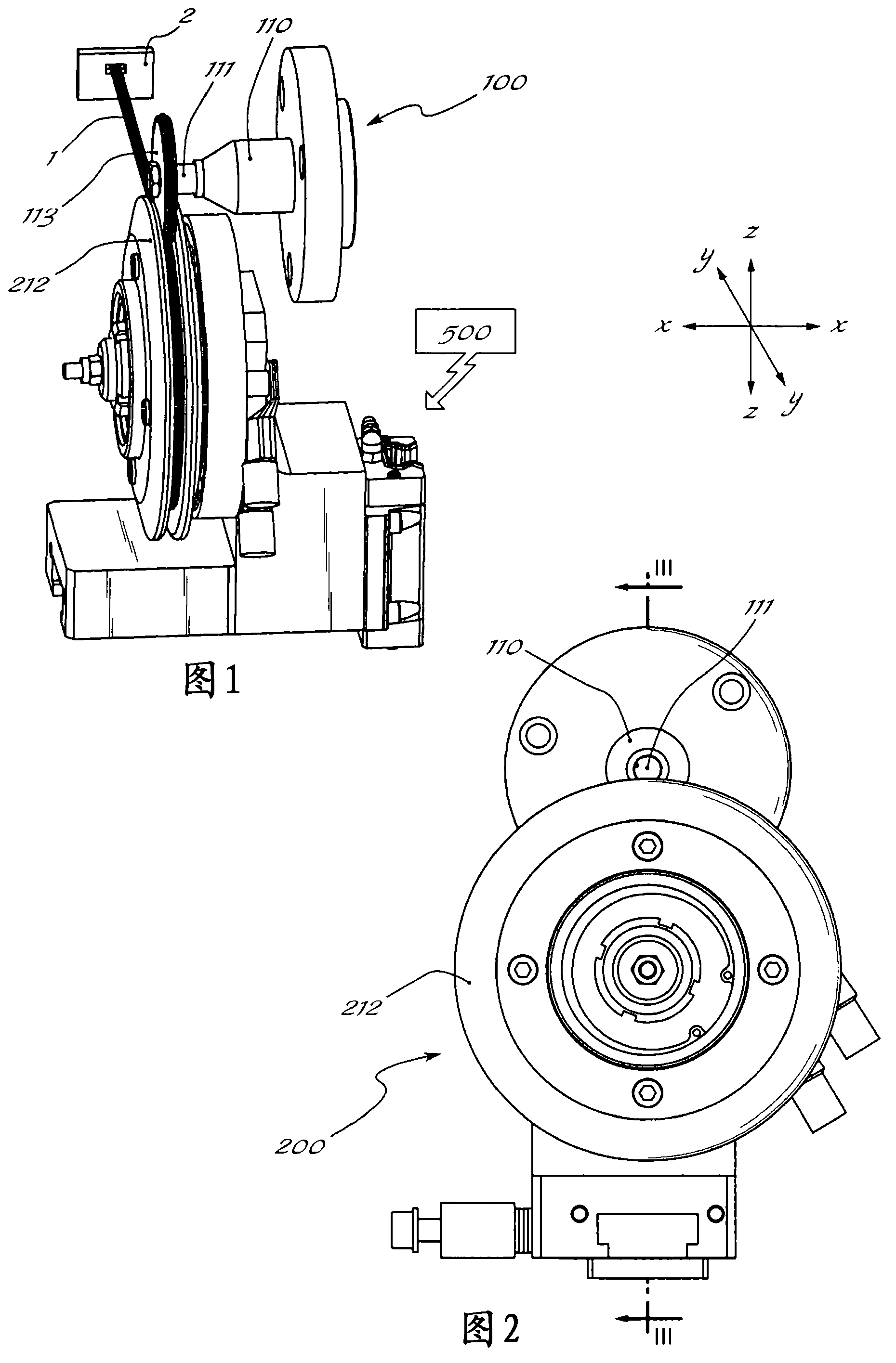
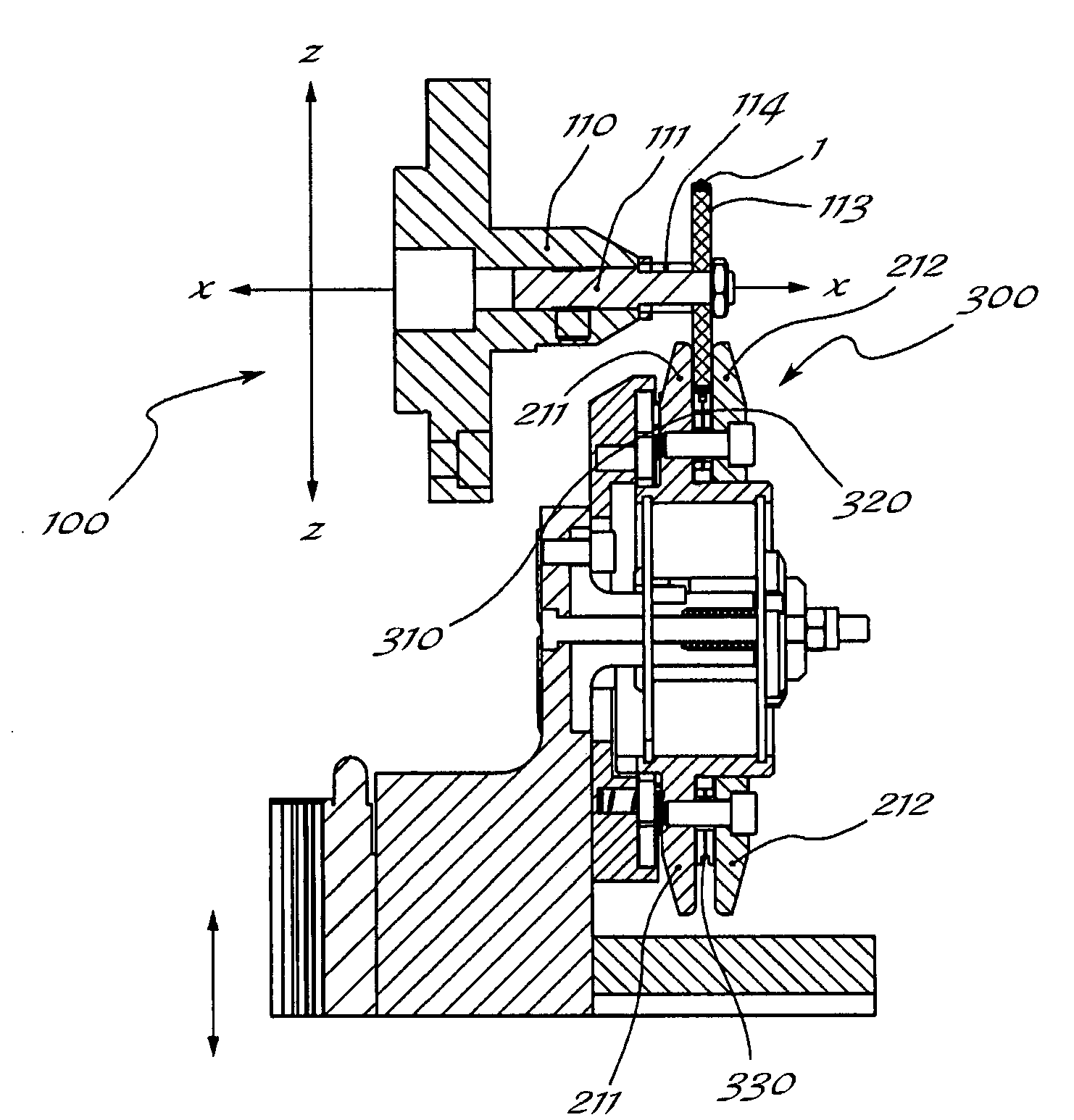
[0020] As shown, for illustrative purposes only and without any limiting meaning, a set of three reference axes are: the longitudinal direction X-X, which corresponds to the axis of rotation of the seal; the vertical direction Z-Z, which is perpendicular to the longitudinal direction and corresponds to the compression and the direction of movement of the welding assembly towards / from the seal; and the radial direction Y-Y, which is perpendicular to the other two directions; the device according to the invention basically comprises:

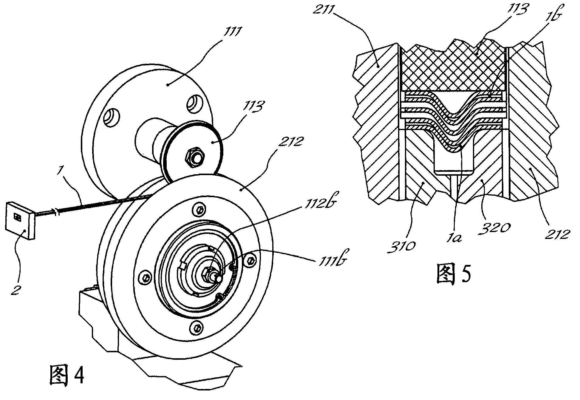
[0021] Assembly 100 for winding a strip 1, in particular a strip 1a made of a material with optimal mechanical properties, such as steel, and a strip 1b with optimal sealing properties, supplied by feeder 2, which itself is of the usual type and not shown and described in detail, the assembly comprises a mandrel 110 which rotates about a longitudinal axis X-X and which has a A pin 111 for supporting a ring 113 of suitable inner and outer diameter ...


PUM


Abstract

Apparatus for welding continuous strips wound on a support ring is disclosed, comprising at least means for feeding the strips to be wound on the support ring, an assembly for winding said strips, an assembly for applying radial pressure onto the strips, comprising a first circular jaw and a second circular jaw, which are arranged opposite each other and spaced in the longitudinal direction by an amount corresponding to the width of the finished seal, and an assembly for welding one of said strips, said pressing assembly and said welding assembly being coaxial, wherein said welding assembly comprises a first electrode and a second electrode which are arranged inside the jaws of the pressing assembly so as to face each other and have a diameter smaller than that of the said jaws, each electrode being insulated both from the other electrode and from the jaws by means of rings made of insulating material, and wherein the electrodes act simultaneously with pressure in the radial direction on the strips.

Description

technical field [0001] The invention relates to a device for welding a strip wound on a support ring, comprising a pressing assembly and a welding assembly, which are arranged in the same circumferential area and act simultaneously on said strip in radial direction bring. Background technique [0002] Various seals are known in the art in the form of rings and capable of providing a static positive seal, for example for connecting pipes. [0003] It is also known that for the industrial manufacture of such seals it is necessary to helically wind two strips which overlap each other and have physical and mechanical properties which differ considerably from each other, in particular the winding has a high mechanical A first strip of strength, for example made of steel, forms a support for a second strip made of a material with the best insulating and sealing properties, but with poorer Mechanical strength. [0004] Machines are also known to form said seals by semi-manual op...

Claims


Application Information

Patent Timeline
Patent Type & Authority Applications(China)
IPC IPC(8): B23K11/00B23K11/31B23K11/36
CPCB23K11/06B23K11/16B23K11/3036B23K11/061B23K2201/04F16J15/125B23K2201/16B23P15/00B23K2101/04B23K2101/16
Inventor G·P·巴罗齐
Owner GSKET
Learn More