Structure of mounting cowl-top cover

A technology for installing structures and front covers, which is applied to the upper structure, upper structure sub-assembly, sealing device, etc., to achieve the effect of improving the appearance aesthetics and firmly engaging the state

Inactive Publication Date: 2013-02-06
NIHON PLAST CO LTD
View PDF10 Cites 13 Cited by
  • Summary
  • Abstract
  • Description
  • Claims
  • Application Information

AI Technical Summary

Problems solved by technology

This rotational force acts on the joint surface of the clamp 53 and the windshield 51, and there is a danger of pee...

Method used


Image

  • Structure of mounting cowl-top cover
  • Structure of mounting cowl-top cover
  • Structure of mounting cowl-top cover

Examples


no. 1 Embodiment approach )

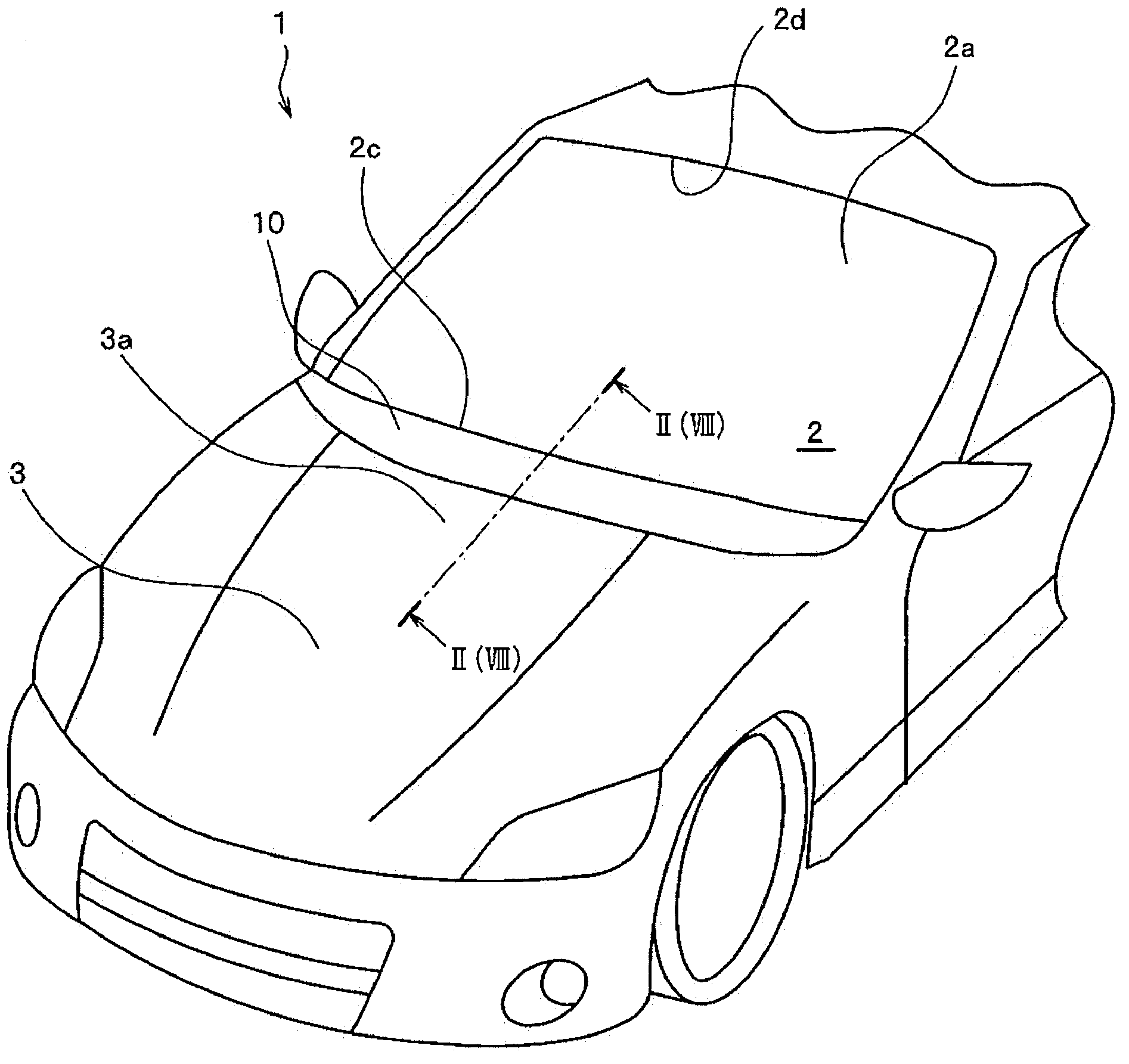
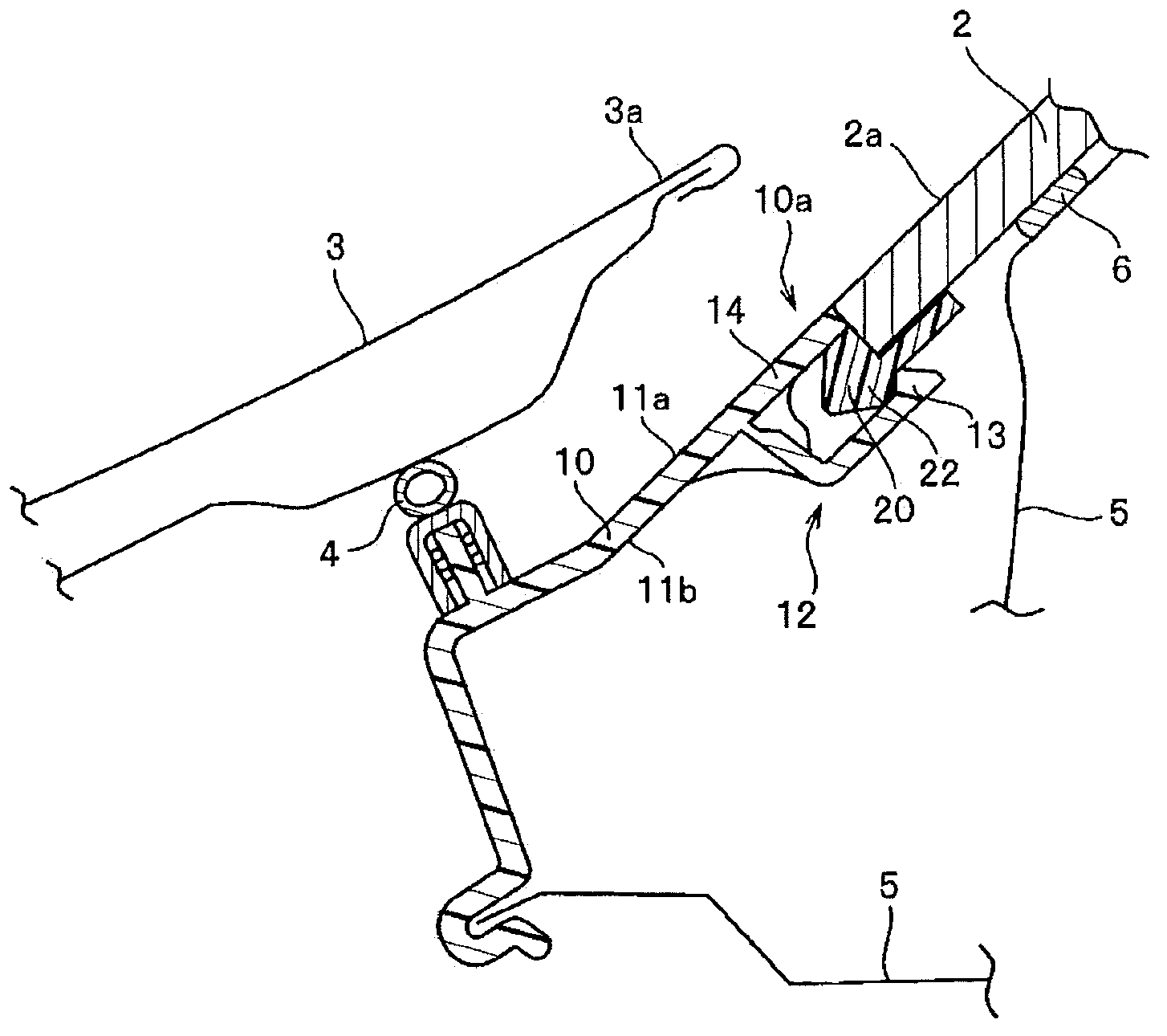
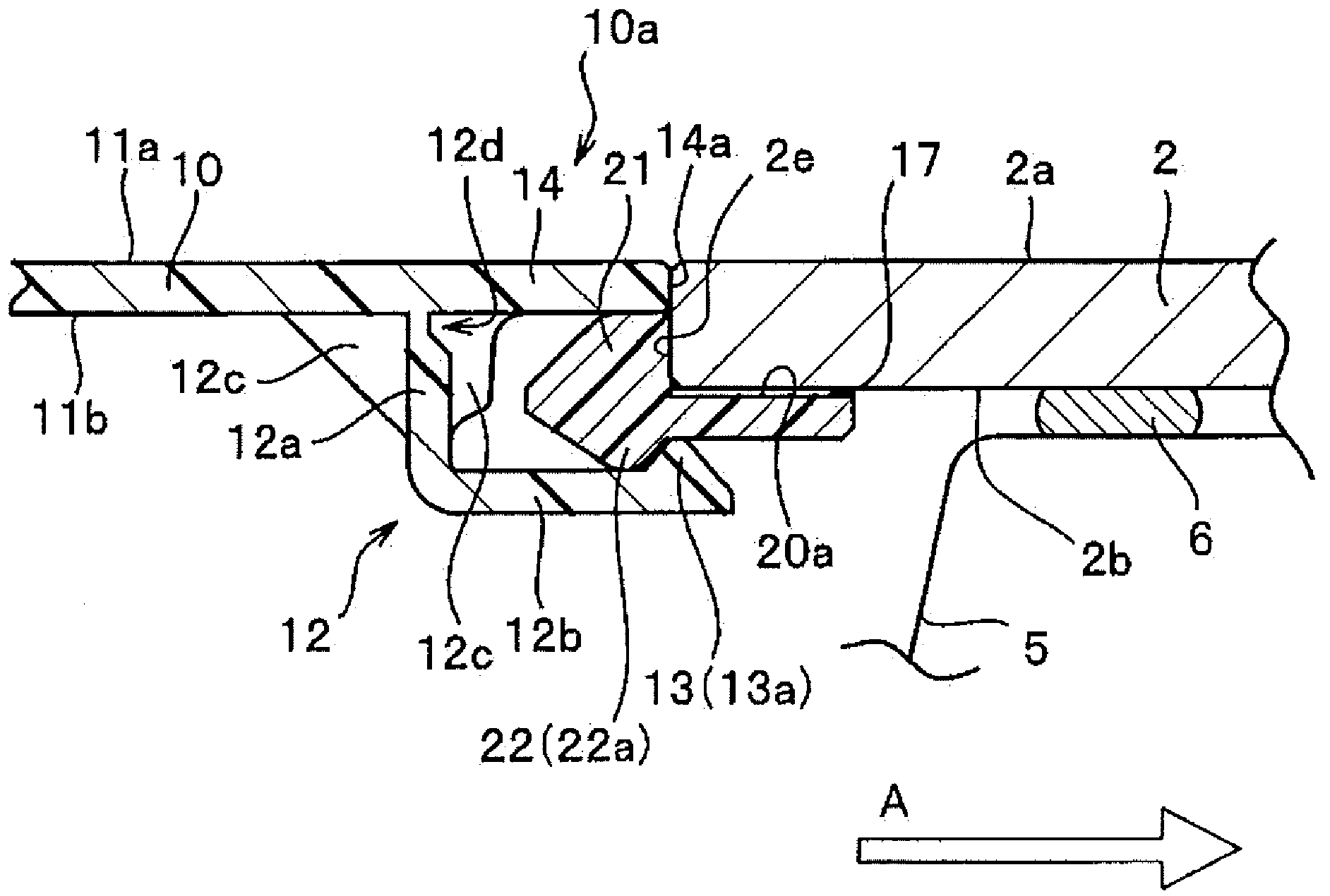
[0084] In the first embodiment, using Figure 2 ~ Figure 4 , a configuration example in which a stepped portion formed on the clamp member is used as an engaged portion to be engaged with the front cover will be described. First, use figure 1 The arrangement structure of the cowl 10 in the vehicle 1 will be described.

[0085] figure 1 It shows a perspective view of the vehicle 1 viewed obliquely from the front. In addition, illustration of wipers and the like is omitted. A windshield 2 is disposed on the front side of the cabin of the vehicle 1, and the windshield 2 is disposed in such a manner that the surface 2a of the windshield 2 faces toward the rear of the vehicle from the lower end 2c of the windshield 2 toward the upper end 2d that is the upper side of the vehicle body. sideways. Furthermore, a cowl panel 10 covers a space between a lower end portion of the windshield glass 2 and a rear end portion 3 a of the engine hood 3 covering the upper opening that partit...

no. 2 Embodiment approach )

[0104] In the second embodiment, like the first embodiment, the engaging portion of the cowl is engaged with the stepped portion formed on the clamp member, but the structure according to the modified example uses Figure 5 ~ Figure 7 Describe it. exist Figure 5 In the illustrated configuration example, the engaged portion 22 of the clamp member 20 is formed as a stepped portion 22b protruding upward, and the engaging portion 13 of the cowl 10 that engages with the stepped portion 22b is formed on the front cover 10. The rear end of the engagement portion 14 is formed in a downward shape. In addition, when the front cover 10 is engaged with the clamp member 20 , the bent piece 12 b of the tongue piece 12 pushes the bottom surface of the front end side of the clamp member 20 upward, and sandwiches the clamp member with the engaging portion 13 . 20. Other configurations have the same configurations as those in the first embodiment, and for the same configurations, descriptio...

no. 3 Embodiment approach )

[0118] In the third embodiment, the engaging portion formed on the front cover is clamped by the engaged portion formed on the clamp member, and the Figure 8 ~ Figure 10 This configuration example will be described. In the third embodiment, the engaging portion formed on the front cover is clamped by the engaged portion formed on the clamping member, and the clamping member is provided in order to obtain a clamping force. The structure of the core material for reinforcement. Furthermore, the structure of the engaging portion on the cowl is sandwiched by the engaged portion, and the structure differs from the structure in the first embodiment in these respects. Other configurations have the same configurations as those in the first embodiment, and for the same configurations, descriptions of the components are omitted by using the component symbols used in the first embodiment.

[0119] as figure 1 of the VIII-VIII section Figure 8 and as Figure 8 Enlarged view of main...


PUM


Abstract

Provided is a cowl-top cover mounting structure that: is capable of arranging a surface of a front glass and a surface of a cowl-top cover so as to be flush with each other; is capable of preventing unlocking of the clip member and the front glass when the cowl-top cover is engaged with the clip member. In present invention, a protrusion portion 21 of a clip member 20 is abutted against an end face 2e of a front glass lower end 2c, and the clip member 20 is fixed to a back face 2b of the front glass 2 via an adhesive agent 17. An engagement portion 13 that is formed in a tongue piece 12 of a cowl-top cover 10 is engaged with a target engagement portion 22 of the clip member 20, and the cowl-top cover 10 is mounted in a state in which a surface 11a of the cowl-top cover 10 and a surface 2a of the front glass 2 are arranged so as to be flush with each other. In addition, an engagement direction is defined as an engagement direction taken along a lengthwise direction oriented from a lower end to an upper end of the front glass.

Description

technical field [0001] The present invention relates to a mounting structure for a cowl panel arranged between a windshield glass and an engine hood of an automobile. Background technique [0002] Conventionally, as a mounting structure for a cowl top cover, a mounting structure in which a lower end portion of a windshield glass is sandwiched and supported by a clamp member formed at a rear end portion of the cowl top cover has been widely used. In this mounting structure, since the lower end of the windshield is sandwiched by the clamping member from the up-down direction, the boundary between the lower end of the windshield and the front cover will inevitably be affected by the thickness of the clamping member. And the expanded structure. [0003] Therefore, a structure that eliminates the expansion of the boundary portion between the lower end of the windshield and the front cover and flattens the surfaces of the two surfaces between the lower end of the windshield and t...

Claims


Application Information

Patent Timeline
IPC IPC(8): B62D25/08
CPCB60J10/02B60R13/04B60J10/70B62D25/08B62D25/081
Inventor 仓田武则芹泽大介
Owner NIHON PLAST CO LTD
Why Eureka
Try Eureka