Plastic flat (round) filament winding device

A technology of winding device and plastic, which is applied in thin material processing, transportation and packaging, and transportation of filamentous materials, etc., can solve the problems of high manufacturing and maintenance costs, high power consumption, and difficulty in weaving, and achieves reduction of power consumption and savings. Effects of Manufacturing and Repair Costs

Inactive Publication Date: 2013-02-06
陈崇锡 +2
View PDF0 Cites 4 Cited by
  • Summary
  • Abstract
  • Description
  • Claims
  • Application Information

AI Technical Summary

Problems solved by technology

[0002] At present, there are two types of plastic flat wire winding devices or plastic round wire winding devices manufactured, sold and used at home and abroad, one is single-spindle winding devices, and the other is cam-type winding devices. The winding device has the advantage of smooth winding bobbins, but has the disadvantages of high power consumption and high manufacturing and maintenance costs. Therefore, the cam type winding device is commonly used at present. The advantage of this device is that the power consumption is relatively low and the manufacturing and maintenance costs are relatively low. The cost is low, but its disadvantage is that the winding bobbin wire is hump-shaped, the weaving process is difficult, the waste is large, and the quality of the finished woven bag is relatively poor. The above two types of winding devices need a small motor to drive each spindle bobbin , generally a plastic flat wire winding unit needs a main motor and hundreds of small bobbin winding motors, the manufacturing and maintenance costs are high and the power consumption is also high

Method used


Image

  • Plastic flat (round) filament winding device
  • Plastic flat (round) filament winding device

Examples


Embodiment Construction

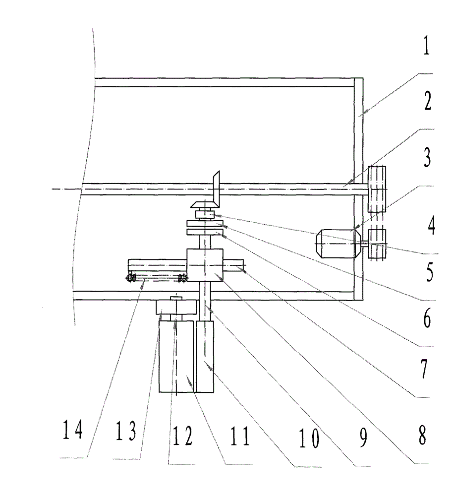
[0009] Embodiments are further described in detail below in conjunction with accompanying drawings

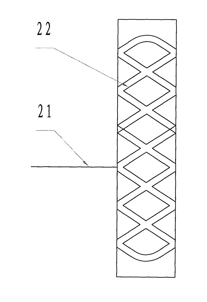
[0010] refer to figure 1 : figure 1 It is a structural schematic diagram of an embodiment of the device of the present invention, combined with figure 2 , 1-base frame, 2-main drive shaft, 3-motor, 4-magnetic main drive plate seat, 5-magnetic main drive plate, 6-magnetic driven plate, 7-linear guide rail, 8-bobbin shaft seat, 9-bobbin shaft, 10-bobbin tube, 11-groove barrel, 12-groove barrel shaft, 13-groove barrel shaft seat, 14-spring, 21-plastic wire, 22-curve groove, motor 3, main drive shaft 2. The magnetic main transmission disk seat 4, the groove cylinder shaft seat 13 and the linear guide rail 7 are fastened and installed on the bracket 1 respectively, and the magnetic main transmission disk 5 is installed in the magnetic main transmission disk seat 4, and the magnetic main transmission disk 5 is connected with the main magnetic transmission disk. The drive shaft 2 ...


PUM


Abstract

The invention discloses a plastic flat (round) filament winding device which comprises a base frame 1, a main driving shaft 2, a motor 3, a magnetic main driving disc seat 4, a magnetic main driving disc 5, a magnetic driven disc 6, a linear guide rail 7, a bobbin shaft seat 8, a bobbin shaft 9, a bobbin 10, a grooved drum 11, a grooved drum shaft 12, a grooved drum shaft seat 13 and a spring 14, wherein the magnetic main driving disc 5 is in transmission with the main driving shaft 2 and the magnetic driven disc 6; the bobbin shaft seat 8 is in fastening connection with a linear bearing mounted on the linear guide rail 7; one end of the bobbin shaft seat 8 is connected with one end of the linear guide rail 7 through a tension spring; and the bobbin 10 is in rolling friction contact with the grooved drum 11. The invention has the benefits as follows: different from a plastic flat filament winding machine in the prior art, which needs a main motor and small winding motors for hundreds of bobbins, the plastic flat (round) filament winding device provided by the invention can be driven by one motor, so as to save a great quantity of small motors, greatly save manufacturing and maintenance costs and reduce power consumption.

Description

technical field [0001] The invention relates to the field of plastic machinery, in particular to a plastic flat (round) wire winding device technical background [0002] At present, there are two types of plastic flat wire winding devices or plastic round wire winding devices manufactured, sold and used at home and abroad, one is single-spindle winding devices, and the other is cam-type winding devices. The winding device has the advantage of smooth bobbin wire, but has the disadvantages of high power consumption and high manufacturing and maintenance costs. Therefore, the cam type winding device is commonly used at present. The advantage of this device is that the power consumption is relatively low and the manufacturing and maintenance costs are relatively low. The cost is low, but its disadvantage is that the winding bobbin wire is hump-shaped, the weaving process is difficult, the waste is large, and the quality of the finished woven bag is relatively poor. The above two...

Claims


Application Information

Patent Timeline
IPC IPC(8): B65H54/06B65H54/40B65H54/74B65H75/10
Inventor 陈崇锡黄美昌周传对
Owner 陈崇锡
Why Eureka
Try Eureka