

Hydraulic brake
A technology of hydraulic brakes and brake discs, applied in the direction of brake types, axial brakes, brake actuators, etc., can solve the problems of high installation cost and difficult production of hydraulic brakes, etc., to save energy and reduce installation costs , The effect of reducing the difficulty of installation
- Summary
- Abstract
- Description
- Claims
- Application Information
AI Technical Summary
Problems solved by technology
Method used
Image

Examples
Embodiment Construction
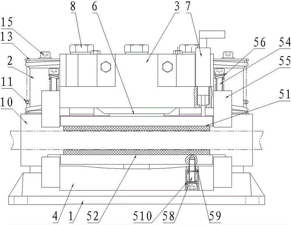
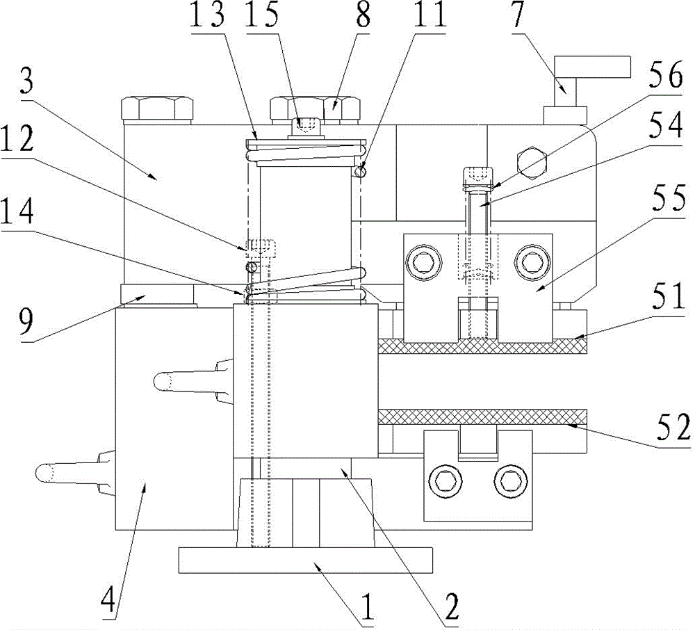
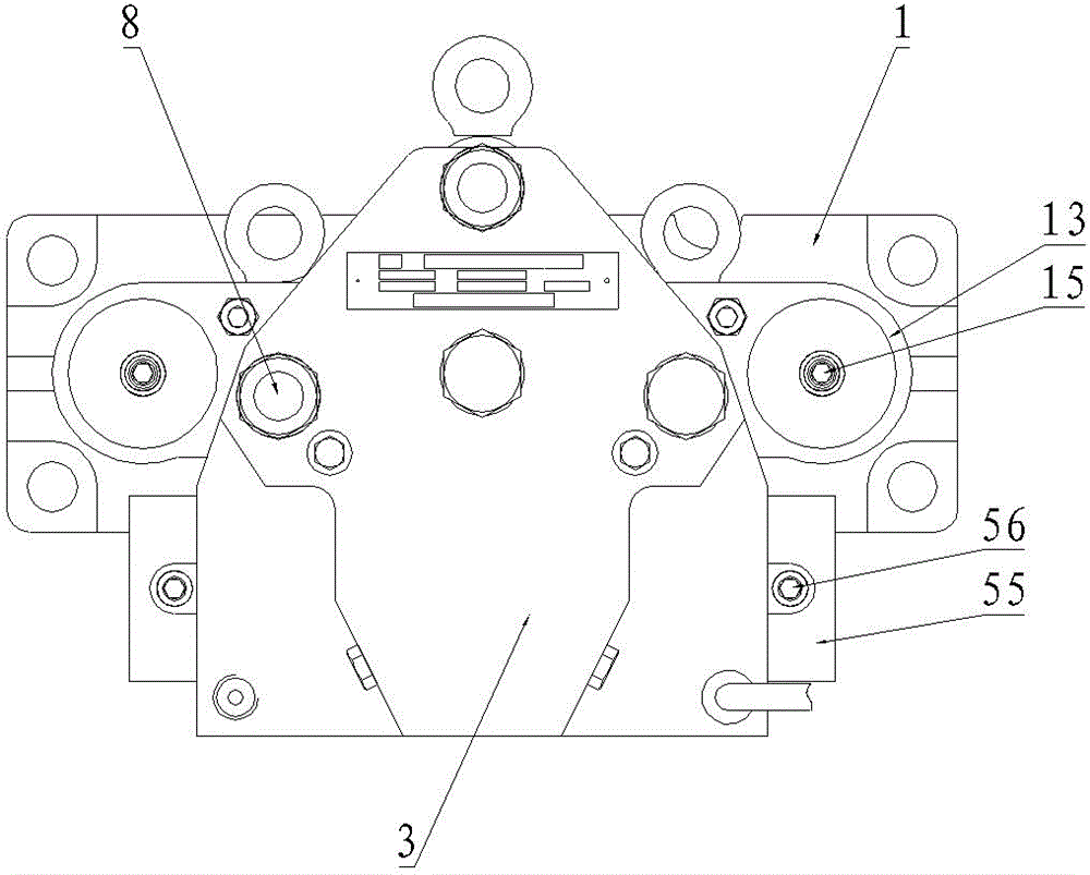
[0018] Embodiments of the hydraulic brake of the present invention: as Figure 1 to Figure 3 As shown, the hydraulic brake includes a frame body and a brake main body. The frame body includes a base 1 extending left and right, and guide columns 2 extending up and down on the left and right sides of the base 1. The brake body is located between the two guide columns. 2, the brake main body includes the active caliper 3 and the passive caliper 4 that are distributed sequentially up and down. There is a gap between the front opposite sides of the active pliers body 3 and the passive pliers body 4, and an active friction plate 51 is installed on the active pliers body 3, and a passive friction plate 52 is installed on the passive pliers body 4, and the active friction plate and the passive caliper body 4 are equipped with The gap between the passive friction plates is the braking space 5 for the insertion of the brake disc. The upper and lower sides of the braking space 5 are resp...
PUM
 Abstract
Description
Claims
Application Information