Rotary circling mechanism

A ring-wrapping and rotating head technology, applied in the field of optical fiber rings, can solve the problems of fiber rings that cannot be separated from manual operation, irregular arrangement of optical fiber rings, and insufficient functions, so as to prevent fiber breakage, ensure consistency, and realize automation.

Active Publication Date: 2013-02-06
武汉长盈通光电技术股份有限公司
View PDF9 Cites 21 Cited by
  • Summary
  • Abstract
  • Description
  • Claims
  • Application Information

AI Technical Summary

Problems solved by technology

[0004] At present, domestic optical fiber winding technology is still immature, and most of the equipment is simple in structure and not perfect in function, and the winding of optical fiber ring cannot be separated from manual operation.
For a precision device such as a fiber optic ring, a slight vibration may cause the fiber ring to be irregularly arranged, over-tensioned, or even broken. Therefore, the equipment and process around the ring directly determine the performance of the fiber optic ring.

Method used


Image

  • Rotary circling mechanism
  • Rotary circling mechanism
  • Rotary circling mechanism

Examples


Embodiment Construction

[0028] The specific embodiments of the present invention will be further described in detail below with reference to the accompanying drawings.

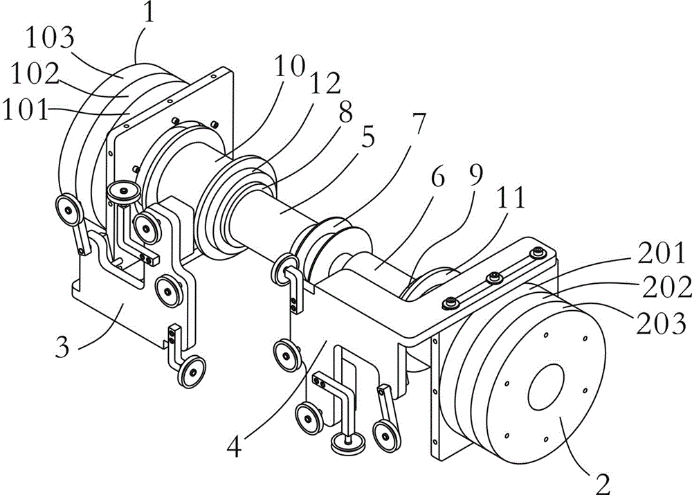
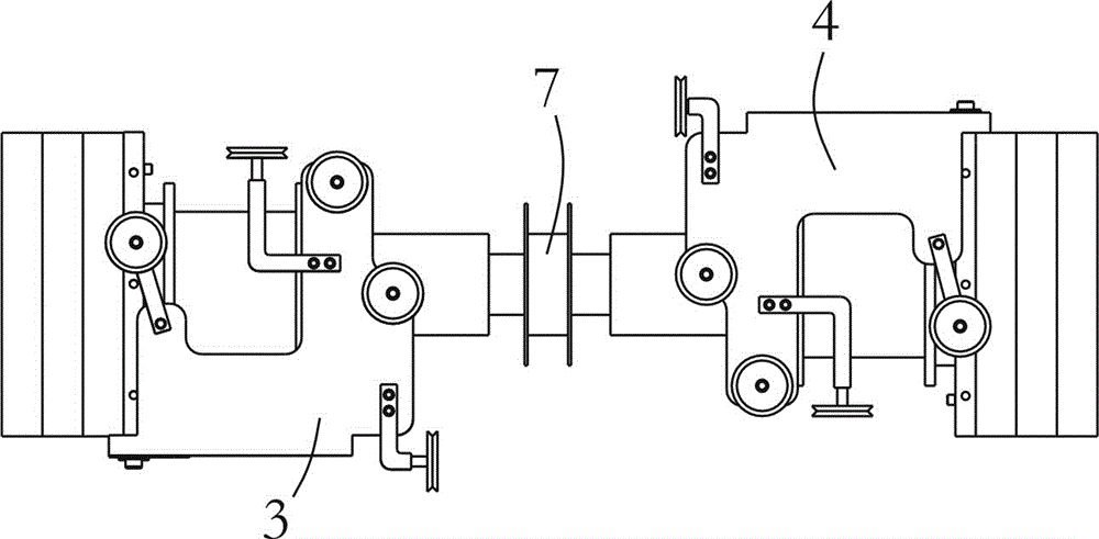
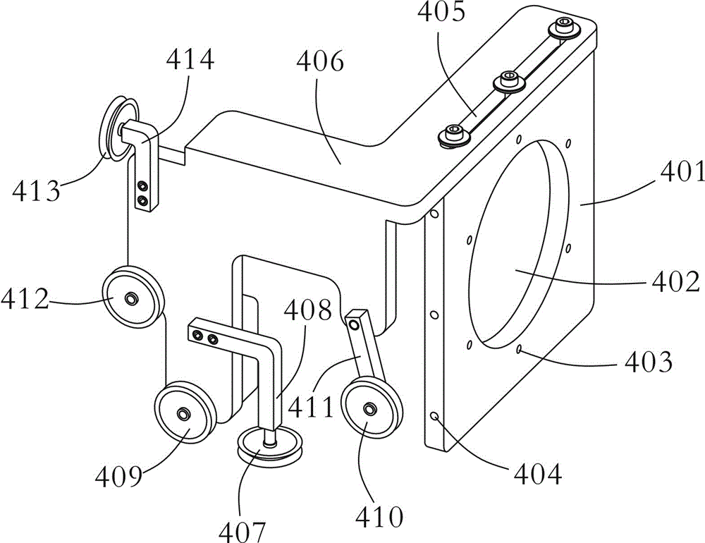
[0029] like Figure 1 to Figure 4 As shown, a rotating loop mechanism of the present invention includes a pair of loop arms with the same structure, which are called a left loop arm and a right loop arm. Taking the right winding arm as an example, it includes a right guide wheel frame 4 and a right rotating head 2 , a right main shaft 6 , a right fiber feeding shaft 9 and a right fiber tray 11 arranged coaxially. The right rotary head 2 is a gear set composed of a right idler gear 201 , a right fiber feeding shaft gear 202 and a right shaft gear 203 . The right idler gear 201 , the right unwinding shaft gear 202 and the right shaft gear 203 are coaxially arranged and do not interfere with each other, and can rotate in forward / reverse directions respectively driven by external power equipment such as motors. The right winding arm ca...


PUM


Abstract

The invention discloses a rotary circling mechanism which comprises one pair of circling arms with the same structure, wherein each circling arm comprises a wheel frame, a rotary head, a main shaft, a fiber releasing shaft and an optical fiber disk; the rotary head, the main shaft, the fiber releasing shaft and the optical fiber disk are coaxially arranged; the rotary head is a gear set composed of a wheel frame gear, a fiber releasing shaft gear and a main shaft gear; the three gears are coaxially arranged, are free from mutual interference and respectively rotate under the driving of external power equipment; the wheel frame gear, the fiber releasing shaft gear and the main shaft gear are respectively fixed with the corresponding wheel frame, the corresponding fiber releasing shaft and the corresponding main shaft; the fiber releasing shaft is sheathed on the main shaft; the optical fiber disk is fixed on the fiber releasing shaft; the wheel frame comprises a wheel frame fixing seat with a large round hole, a rotary head and a main shaft; the fiber releasing shaft and the optical fiber disk pass through the large rough hole and are respectively arranged on the two edges of the wheel frame fixing seat; the main shafts of one pair of circling arms are coaxially arranged; the ends of the circling arms are opposite; the wheel frame fixing seat is also connected with a wheel fixing frame; and the wheel fixing frame is positioned on one side of the main shaft and is provided with a plurality of fiber guide wheels used for guiding optical fibers led from the optical fiber disk to an optical fiber ring skeleton.

Description

technical field [0001] The invention relates to an optical fiber ring in an optical fiber sensor such as a fiber optic gyroscope, in particular to a rotating ring mechanism, which can cooperate with a ring winding machine to wind the optical fiber ring. Background technique [0002] Fiber optic gyroscope is a high-precision inertial sensor for measuring attitude and orientation. It has been widely used in robots, ships, aircraft, missiles and other fields. [0003] As the core sensing part of the fiber optic gyroscope, the fiber optic ring directly affects the measurement accuracy of the fiber optic gyroscope. Therefore, many requirements are put forward in practical applications, such as a large extinction ratio and a better mutuality. There are many winding methods for optical fiber rings, such as flat winding, quadrupole symmetrical winding, octupole symmetrical winding, etc. Among them, the quadrupole symmetrical winding method is relatively mature and is the mainstream...

Claims


Application Information

Patent Timeline
Patent Type & Authority Applications(China)
IPC IPC(8): G01C19/72
Inventor 郭伟华杨娟李宏李家乐周红伟曲勇军汪洪海皮亚斌
Owner 武汉长盈通光电技术股份有限公司
Why Eureka
Try Eureka